Introduction to SB03 Photoelectric Sensor
The SB03 photoelectric sensor is a versatile and reliable component widely used in industrial automation for detecting objects, counting, and positioning. Its robust design ensures stable performance in various environmental conditions, including dusty or humid settings. Understanding the correct wiring procedure is crucial for maximizing sensor functionality and ensuring system safety. This guide provides a detailed, step-by-step approach to wiring the SB03 sensor, covering both theoretical principles and practical implementation.
Understanding SB03 Sensor Pin Configuration
The SB03 sensor typically features a standard 4-pin M12 connector, which is common in industrial sensors for its durability and ease of connection. The pinout configuration generally includes: Pin 1 for the positive supply voltage (brown wire), Pin 2 for the output signal (black wire), Pin 3 for the negative supply or ground (blue wire), and Pin 4 as an auxiliary or complementary output (white wire). However, variations may exist based on the specific model (e.g., NPN or PNP output types). Always refer to the manufacturer's datasheet to confirm the exact pin assignments before proceeding with wiring.
Required Tools and Materials for Wiring
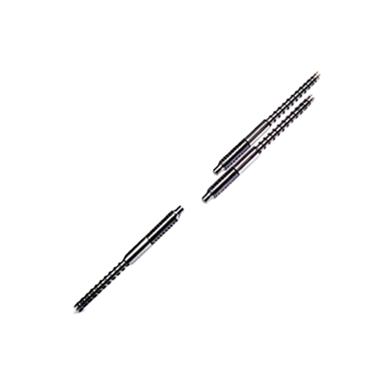
To wire the SB03 sensor effectively, gather the necessary tools and materials: a screwdriver set, wire strippers, crimping tools, M12 connector plugs (if not pre-attached), shielded cables (recommended for noise reduction), and a DC power supply matching the sensor's voltage range (typically 10-30V DC). Additionally, ensure you have personal protective equipment, such as safety glasses and insulated gloves, to prevent electrical hazards during installation.
Step-by-Step Wiring Procedure
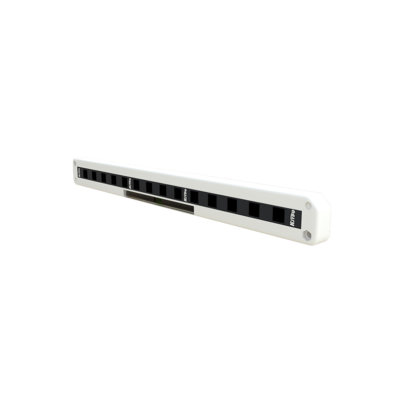
Begin by disconnecting all power sources to avoid electrical shocks. Identify the sensor's pins using the datasheet and prepare the cables by stripping the insulation to expose about 5-7mm of wire. Connect the brown wire to the positive terminal of the power supply and the blue wire to the negative terminal. For the output, link the black wire to the load device (e.g., PLC input or relay), ensuring proper grounding if using shielded cables. If the sensor has a complementary output (white wire), connect it as per the system requirements. Secure all connections with crimps or screws to prevent loose contacts.
NPN vs. PNP Output Wiring Differences
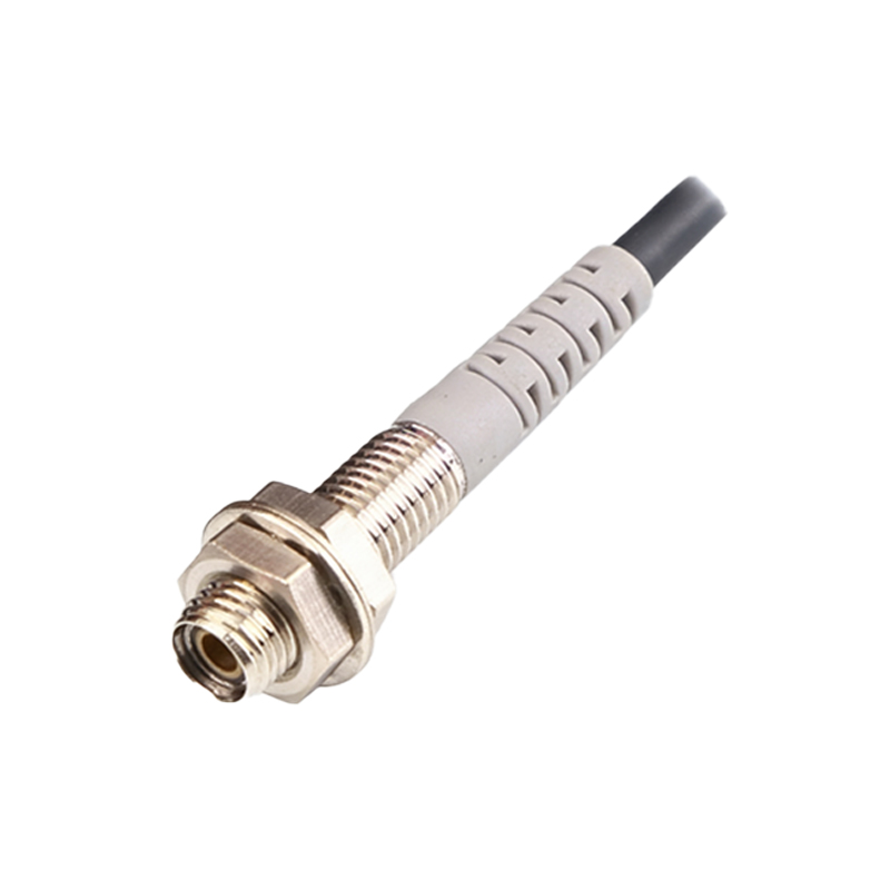
The SB03 sensor is available in both NPN (sinking) and PNP (sourcing) output configurations, which affect wiring. For NPN types, the output switches the negative side; connect the black wire to the load, and the load's other side to positive voltage. For PNP types, the output switches the positive side; connect the black wire to the load, and the load's other side to ground. Miswiring can lead to malfunction or damage, so verify the sensor's output type on its label or documentation before installation.
Testing and Troubleshooting Connections
After wiring, apply power and test the sensor by placing an object within its detection range. Use a multimeter to check voltage levels at the output pin: it should switch between high and low states upon detection. If the sensor fails to operate, inspect for loose wires, incorrect polarity, or power supply issues. Ensure the load impedance matches the sensor's specifications to avoid overloading. For persistent problems, consult the troubleshooting section of the manual or contact technical support.
Safety Precautions and Best Practices
Always adhere to industrial safety standards, such as IEC 60204-1, when wiring the SB03 sensor. Use insulated tools and avoid exposed conductors to prevent short circuits. Implement proper cable management, such as routing wires away from high-voltage lines to reduce electromagnetic interference. Regularly inspect connections for wear or corrosion, especially in harsh environments. Following these practices enhances sensor longevity and system reliability.
Applications and Integration Tips
The SB03 sensor is ideal for applications like conveyor belt monitoring, packaging machinery, and robotic assembly lines. For integration, consider environmental factors: in dusty areas, use sensors with higher IP ratings and clean lenses periodically. For long-distance wiring, use thicker cables to minimize voltage drop. Pair the sensor with compatible controllers, such as PLCs, and configure input settings accordingly. This ensures seamless operation within automated systems.
Conclusion and Further Resources
Proper wiring of the SB03 photoelectric sensor is essential for optimal performance in industrial setups. By following this guide, technicians can ensure accurate detection and system safety. For more details, refer to the official product manual or online tutorials from reputable sources. Continuous learning about sensor technologies helps in adapting to evolving automation demands.