Understanding KIP3000 Photoelectric Sensor Fault Indicators
Modern industrial automation relies heavily on the precision and reliability of photoelectric sensors like the KIP3000 series. These devices play a critical role in object detection, positioning, and process control. When a fault occurs, the sensor communicates an issue through specific fault codes, typically indicated by LED status lights or communication interface outputs. Recognizing these indicators is the first step in effective troubleshooting. A steady or flashing pattern on the sensor's diagnostic LED often corresponds to a specific error condition, signaling problems ranging from power supply issues to optical alignment failures or internal component malfunctions. Operators and maintenance personnel must consult the official KIP3000 manual to decode these light patterns accurately, as misinterpretation can lead to incorrect corrective actions and prolonged downtime.
Common Fault Codes and Their Primary Causes
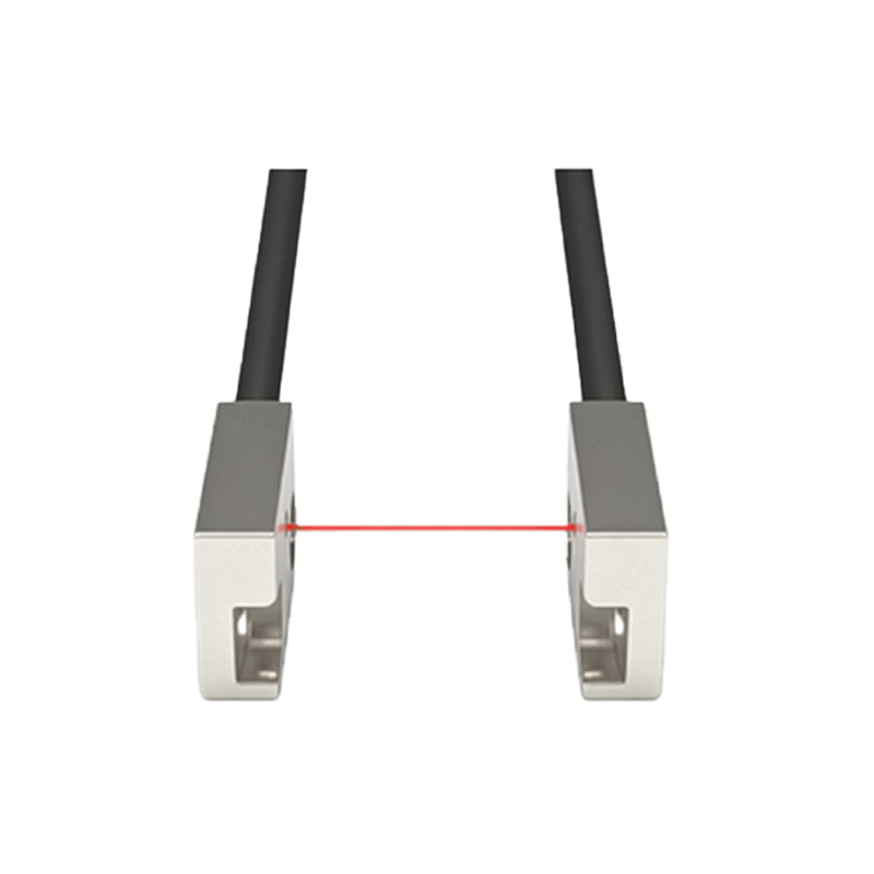
Several recurring fault codes are frequently encountered with KIP3000 sensors in field applications. Code E01 or a similar LED sequence often indicates a "Supply Voltage Low" condition. This can result from an unstable power source, voltage drops across long cable runs, or insufficient current capacity from the power supply unit. Another prevalent code, often signaled as E02, points to a "Short-Circuit" or overload at the output stage. This may be caused by a faulty connected load, such as a relay or PLC input module, or by moisture ingress causing a short. Code E03 typically relates to "Sensor Overload" or excessive ambient light interference, where strong external light sources saturate the receiver, preventing proper detection. Understanding these root causes is essential for targeted diagnostics.
Systematic Troubleshooting Procedure for Fault Codes
A methodical approach is vital when addressing KIP3000 fault codes. Begin by verifying the basic installation parameters: ensure the sensor is receiving power within its specified voltage range (e.g., 10-30 VDC) using a multimeter. Check all wiring connections for tightness and corrosion, and inspect cables for damage. For optical faults, clean the lens of both the transmitter and receiver with appropriate materials to remove dust, oil, or debris. Next, evaluate the sensing environment. Adjust the sensor's sensitivity potentiometer if available, and ensure the detected object falls within the specified size, reflectivity, and distance parameters. Temporarily shield the sensor from intense ambient light or consider using a sensor with a modulated light source to mitigate interference. If the fault persists, perform an isolation test by connecting the sensor to a known-good power supply and a minimal test load.
Resolving Power and Wiring Related Faults
Power-related errors are among the most common. For a low-voltage fault (E01), measure the voltage directly at the sensor's terminals during operation. If the voltage is low, troubleshoot upstream by checking the power supply rating, fuses, and circuit breakers. Ensure wire gauge is adequate for the current and distance. For output short-circuit faults (E02), disconnect the load wire from the sensor's output terminal. If the fault code clears, the issue lies in the external wiring or the load device. Use an insulation tester to check for shorts to ground or between conductors. Remember to always follow lock-out/tag-out (LOTO) procedures before handling any electrical connections to ensure safety.
Addressing Optical and Environmental Interference Issues
Faults stemming from the optical path or environment require a different strategy. If the sensor indicates an overload or instability (E03), first confirm the alignment between the emitter and receiver for through-beam models, or the alignment to the target for reflective models. Misalignment is a frequent culprit. For diffuse reflective sensors, ensure the target object's surface properties have not changed. Use alignment tools if provided. To combat ambient light interference, install protective shrouds or hoods around the sensor. Consider switching to a fiber optic model for extremely harsh or space-constrained environments. Regularly scheduled maintenance for lens cleaning and environmental assessment can prevent many of these optical fault codes from occurring.
Advanced Diagnostics and When to Seek Replacement
If basic troubleshooting does not resolve the fault code, advanced diagnostics may be necessary. This could involve monitoring the sensor's output with an oscilloscope to check for signal integrity or using the manufacturer's proprietary diagnostic software if the sensor supports digital communication. Compare the behavior of the faulty sensor with a known-working unit of the same model under identical conditions. Persistent fault codes after exhaustive troubleshooting often indicate an internal failure, such as a degraded LED emitter, damaged receiver element, or faulty logic circuit. At this point, sensor replacement becomes the most cost-effective solution to restore system reliability. Always ensure a replacement sensor has the exact same specifications (e.g., sensing mode, output type, sensing range) as the original.
Preventive Maintenance to Minimize Fault Code Occurrence
Proactive maintenance significantly reduces the frequency of fault codes. Establish a routine schedule to inspect sensor mounting for stability and vibration, which can loosen connections over time. Keep optical components clean according to the plant's maintenance calendar. Periodically verify the stability of the power supply system and check for environmental changes, such as new machinery that might cause electrical noise or introduce new light sources. Documenting all fault occurrences, actions taken, and resolutions creates a valuable knowledge base for faster future troubleshooting and helps identify recurring systemic issues within the automation line.