Understanding Proximity Switch Sensor Fundamentals
Proximity switch sensors are indispensable components in modern industrial automation, providing non-contact detection of metallic or non-metallic objects. Unlike mechanical limit switches, they operate without physical contact, leading to enhanced reliability, longer service life, and faster response times. The three-wire configuration is the most prevalent in industrial settings due to its balance of performance and simplicity. These sensors are categorized primarily by their sensing technology: inductive (for metals), capacitive (for various materials including liquids), and ultrasonic. A solid grasp of their operating principle—where an electromagnetic field or ultrasonic wave is disturbed by a target, triggering a switching action—is crucial before delving into wiring specifics. This foundational knowledge ensures correct selection and application across diverse machinery and control systems.

Decoding the Three-Wire Configuration
The three wires in a standard DC proximity sensor are distinctly color-coded for universal identification: brown, blue, and black. The brown wire is designated for the positive supply voltage, typically ranging from 10 to 30 VDC. The blue wire is always connected to the common ground or negative terminal of the power supply. The critical third wire, black, is the signal output line. Its function depends on the sensor's switching logic. In a normally open (NO) configuration, the black wire provides a positive voltage signal (sourcing) when a target is detected. Conversely, in a normally closed (NC) configuration, the signal voltage is present until a target interrupts it. Understanding whether your sensor is PNP (sourcing) or NPN (sinking) is paramount, as this determines how the black wire interacts with the programmable logic controller (PLC) or relay input.
Step-by-Step Wiring Procedure and Best Practices
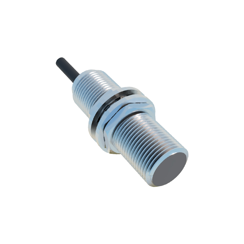
A systematic approach to wiring ensures operational safety and sensor longevity. First, always disconnect power to the circuit. Identify the sensor's specifications, notably the operating voltage and output type (PNP/NPN). Connect the brown wire to the positive DC supply terminal and the blue wire to the negative DC supply terminal. The black output wire is then connected to the input channel of your controller. For a PNP sensor, the black wire connects to the PLC's input, and the input's common is tied to ground. For an NPN sensor, the black wire connects to the PLC input, and the input's common is tied to the positive supply. Always use shielded cables in electrically noisy environments, grounding the shield at only one end to the cabinet ground. Secure connections with appropriate ferrules and ensure wires are routed away from high-power cables to prevent electromagnetic interference.
Integrating with PLCs and Control Systems
Successful integration into a control system requires matching the sensor's output type with the PLC's input module. Most modern PLCs accept both PNP and NPN inputs, but the wiring differs. For a PNP sensor connected to a sinking input module, the black wire goes to the input point, and the module's common is connected to ground. This completes the circuit, allowing current to flow from the sensor into the PLC. When using an NPN sensor with a sourcing input module, the black wire is connected to the input, and the module's common is connected to the positive voltage. The sensor then sinks current from the PLC input to ground. Always consult both the sensor and PLC datasheets. Incorrect pairing can lead to malfunction or damage. Diagnostic LEDs on both the sensor and PLC input module are invaluable for troubleshooting connectivity and detection issues.
Common Troubleshooting and Diagnostic Techniques
Even with correct wiring, issues may arise. A systematic diagnostic approach is key. If the sensor fails to detect targets, first verify power is present between brown and blue wires using a multimeter. Next, check the output signal on the black wire relative to blue (ground) when a target is presented. For a PNP sensor, the voltage should switch to near the supply voltage. For NPN, it should drop to near zero volts. If no output change occurs, the sensing face may be dirty, the target may be outside the rated sensing distance, or the sensor may be damaged. Consistent false triggering often indicates electrical noise interference; verify proper shielding and grounding. Also, ensure the target material and size are within specifications, especially for inductive sensors which have different correction factors for various metals. Regularly inspecting mechanical alignment and environmental factors like temperature and vibration can prevent many common failures.