Introduction to Photoelectric Sensor Symbols
Photoelectric sensors are essential components in industrial automation, widely used for detection, positioning, and counting tasks. Understanding their symbols and graphics is crucial for engineers and technicians when designing, reading, or interpreting electrical schematics and system diagrams. These symbols provide a standardized visual representation of sensor types, functions, and connections, ensuring clear communication across technical documentation. This guide offers a comprehensive overview of common photoelectric sensor symbols, categorized by technology and application, to aid in accurate identification and implementation.
Basic Symbol Elements and Conventions
The foundation of photoelectric sensor symbols lies in basic graphical elements established by international standards such as IEC 60617 and ANSI/IEEE 315. A typical symbol includes a circle or rectangle representing the sensor housing, with internal markings indicating the sensing principle. Arrows often denote the direction of light emission and reception. Connection points, shown as lines or terminals, represent power supply, output signals, and sometimes configuration interfaces. It's important to note that while core elements are standardized, variations may exist between manufacturers or specific diagram types, so always refer to the accompanying legend or datasheet for precise interpretation.
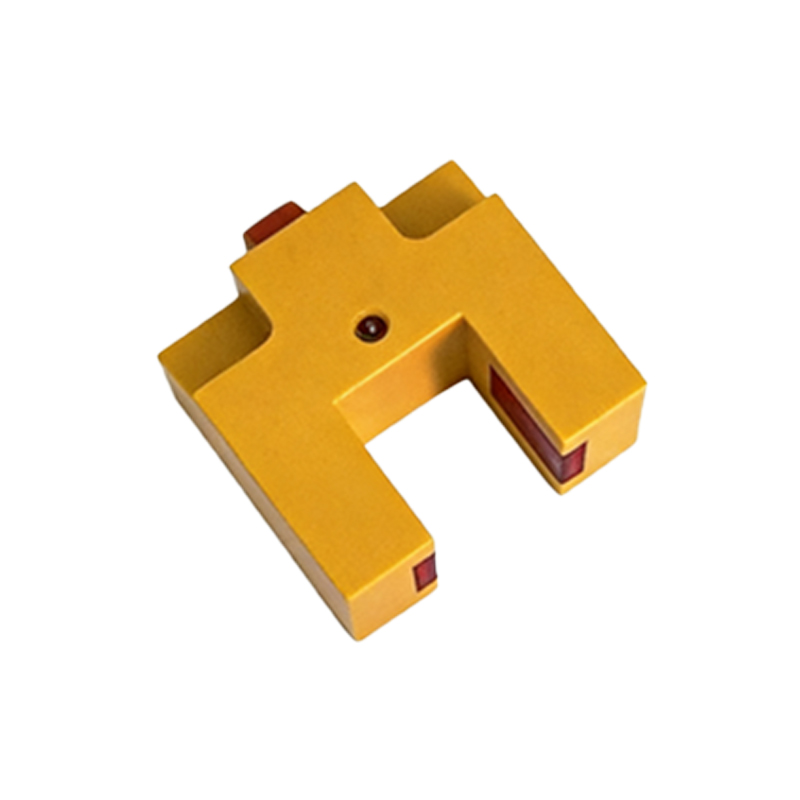
Through-Beam Sensor Symbols
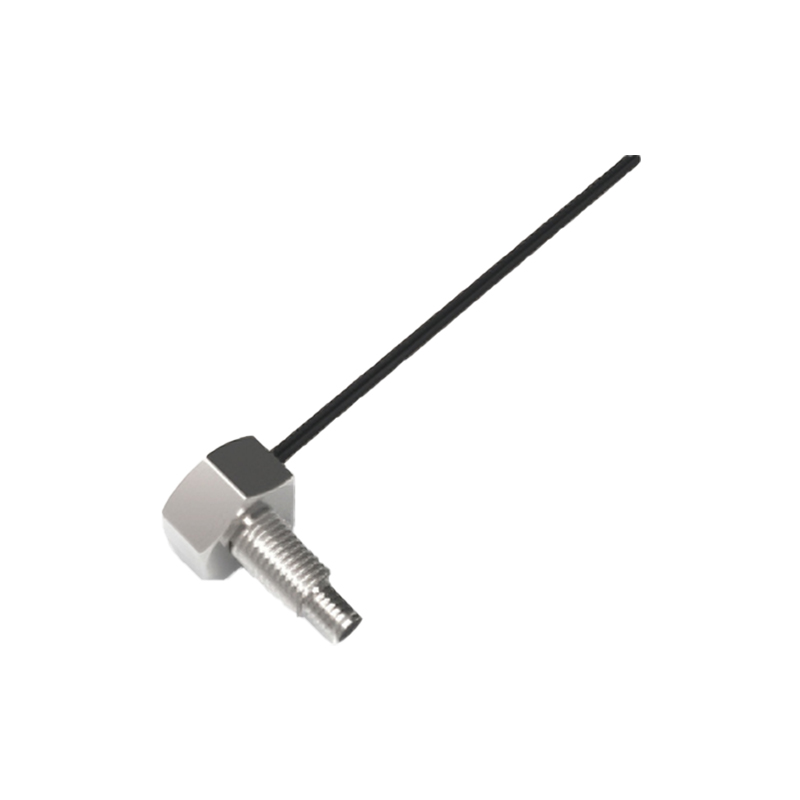
Through-beam (or opposed) photoelectric sensors consist of separate emitter and receiver units. In symbols, the emitter is typically shown as a circle with a light-emitting diode (LED) icon and an outward-pointing arrow. The receiver is depicted similarly but with an inward-pointing arrow or a phototransistor symbol. They are often connected by dashed lines indicating the light beam path. The symbol may include labels like "Tx" for transmitter and "Rx" for receiver. Output terminals on the receiver symbol indicate the switching signal, usually marked as NO (normally open) or NC (normally closed) contacts, depending on the sensor's logic.
Reflective Sensor Symbols
Reflective sensors, including retro-reflective and diffuse-reflective types, combine emitter and receiver in a single housing. Their symbol is usually a single rectangle or circle containing both the LED and phototransistor icons, with arrows showing emitted light and its reflection from a target. Retro-reflective symbols often include a stylized representation of a reflector (like a corner-cube) opposite the sensor. Diffuse-reflective symbols might show the light beam terminating at an irregular surface, symbolizing the target. These symbols frequently incorporate additional markings to indicate sensing range or background suppression features, such as "BGS" for background suppression models.
Fiber Optic Sensor Symbols
Fiber optic photoelectric sensors use optical fibers to guide light to and from the sensing point. Their symbols are distinct, showing the amplifier unit separately from the fiber optic cables. The amplifier symbol resembles a standard sensor but includes specific terminals for fiber connection, often depicted as small circles or plugs. The fiber cables themselves are shown as lines, sometimes with a light beam core indicated. Symbols for different fiber head types (e.g., through-beam, coaxial, or side-view heads) include unique end-shapes to illustrate their function. These symbols emphasize the separation between electronics and sensing point, crucial for applications in harsh environments.
Output Configuration Symbols
Photoelectric sensor symbols also convey output type and configuration. Common output symbols include transistor icons (NPN or PNP) with collector and emitter markings for solid-state outputs, or relay contact symbols for electromechanical outputs. Digital symbols like "OUT" or "Q" may be used, often accompanied by polarity indicators (+/-). Analog output sensors show a variable resistor or current source symbol. Some advanced symbols incorporate logic function indicators, such as a timer icon for sensors with delay functions, or a hysteresis curve for window comparators. Color coding or line styles (solid vs. dashed) can further differentiate between output states or signal types.
Special Function and Advanced Sensor Symbols
Modern photoelectric sensors include specialized functions, represented by additional graphical elements. Safety-rated sensors, for example, feature a yellow triangle with an exclamation mark or specific codes like "Type 4" per ISO 13849. Distance-measuring sensors may include a ruler icon or waveform symbol. Color sensors show a prism or RGB color wheel. Luminescence or contrast sensors might display a stylized light spectrum. Communication-enabled sensors incorporate bus symbols (e.g., IO-Link, PROFINET icons) near connection points. These enhanced symbols help quickly identify sensor capabilities within complex system diagrams.
Wiring and Connection Diagram Symbols
In wiring diagrams, photoelectric sensor symbols are integrated with connection details. These symbols explicitly show terminal numbers or letters (e.g., V+, 0V, OUT, M) alongside the graphical representation. Cable entries are indicated by small circles or dots, with wire colors sometimes noted. Shielded cables are shown with a ground symbol or dashed enclosure. Diagrams for programmable sensors include symbols for teach-in buttons or configuration ports, often depicted as switches or USB-style icons. Understanding these detailed symbols is essential for correct installation, troubleshooting, and integration into control systems like PLCs.
Application in Circuit and Layout Diagrams
Within full circuit or panel layout diagrams, photoelectric sensor symbols are placed in context. They connect to power supply symbols (battery or AC source icons) and load symbols (relay coils, PLC input modules). The sensor's position relative to mechanical components, like conveyors or actuators, might be indicated using dashed linking lines. In layout diagrams, the symbol's placement approximates the physical installation location, with notes on mounting orientation. Symbols for sensor arrays or networks show multiple units connected via common bus lines, emphasizing system-level interaction rather than individual sensor details.
Conclusion and Best Practices
Mastering photoelectric sensor symbols enhances efficiency in design, installation, and maintenance. Always cross-reference symbols with manufacturer documentation, as proprietary variations exist. Use standardized symbol libraries in CAD software to ensure consistency. When creating custom diagrams, include a clear legend explaining all symbols used. Regular training on symbol updates from standards bodies helps maintain accuracy. By leveraging this symbolic language effectively, engineers can ensure robust communication, reduce errors, and optimize automation system performance across diverse industrial applications.