Understanding the 180T Photoelectric Sensor
The 180T series photoelectric sensor is a versatile and robust component widely used in industrial automation for object detection, counting, and positioning. Its operation is based on the principle of emitting a light beam, typically infrared or visible LED, and detecting changes in the received light intensity caused by the presence or absence of a target object. The "180T" designation often refers to a specific form factor or housing style, commonly a cylindrical threaded barrel, providing durability and ease of installation in various environments. Key internal components include the emitter, receiver, and a signal processing circuit. Understanding its fundamental working modes—through-beam, retro-reflective, and diffuse (proximity)—is crucial before attempting any adjustment, as the setup procedure varies significantly between them.
Pre-Adjustment Safety and Preparation
Prior to any adjustment procedure, ensure all safety protocols are strictly followed. Disconnect the sensor from its power source to prevent electrical shock or accidental machine activation. Verify the sensor model and its specifications from the datasheet, confirming it is indeed a 180T and noting its voltage range (e.g., 10-30V DC), output type (PNP/NPN, NO/NC), and sensing range. Gather necessary tools: a small flat-head or Phillips screwdriver for potentiometer adjustment, a voltmeter or the sensor's indicator LED for feedback, and the target object to be detected. Clean the sensor's lens with a soft, dry cloth to remove any dust, oil, or debris that could impair its performance. Mount the sensor securely in its intended location, ensuring proper alignment for the chosen sensing mode.
Initial Wiring and Power Connection
Correct wiring is fundamental. Reconnect the power supply according to the sensor's pinout diagram. Typically, a 3-wire DC sensor will have brown (V+), blue (V- or ground), and black (output signal) wires. For a 4-wire version, an additional white wire might be for a second output or function. Double-check the polarity to avoid damaging the unit. Once powered, observe the sensor's status LED. A steady or blinking green light often indicates power and standby mode, while a red or orange light may signify an output active state or an alarm condition. Refer to the manual for specific LED code interpretations. This initial check confirms basic functionality before fine-tuning.
Adjusting Sensitivity via Potentiometer
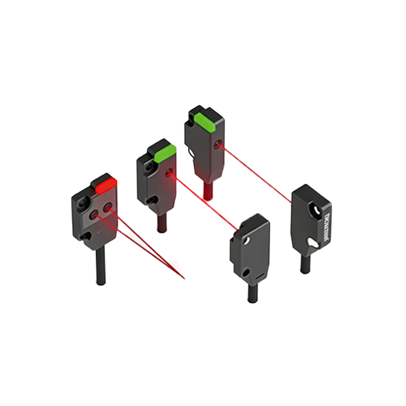
The core of adjusting a 180T photoelectric sensor is the sensitivity potentiometer, usually accessible through a small hole on the body of the sensor. This control adjusts the threshold at which the receiver triggers an output signal. Using the target object, place it at the standard detection distance. Insert the screwdriver into the potentiometer. Turn it slowly clockwise to increase sensitivity (detecting weaker signals or smaller objects) and counter-clockwise to decrease sensitivity. The goal is to achieve a stable detection of the desired target while ignoring background interference or environmental noise like ambient light. Use the sensor's output indicator LED as a guide; it should illuminate consistently when the target is present and turn off when absent. Make incremental adjustments and test repeatedly.
Setting the Response Time and Function Mode
Many 180T sensors feature a second potentiometer or DIP switches to set response time (also called on-delay/off-delay) and operating function mode. The response time adjustment helps filter out rapid vibrations or bouncing objects, ensuring a clean, sustained output signal. A longer delay prevents chattering. The function mode switch might allow selection between light-on/dark-on operation (output activates when light is received or blocked), or a timing function. For a standard presence detection application, the dark-on mode (object interrupts beam, output turns on) is common for through-beam and retro-reflective types. Consult the specific product manual to locate these controls and set them according to your application's timing and logic requirements.
Alignment and Beam Positioning Techniques
Precise alignment is critical, especially for through-beam and retro-reflective types. For through-beam, align the emitter and receiver units directly opposite each other until the receiver's alignment indicator LED is at its brightest. For retro-reflective models, align the sensor perpendicular to the reflector tape or panel. Diffuse sensors require careful positioning relative to the target's surface properties and angle. Use the target object and slowly move it through the sensing field while monitoring the output. Fine-tune the sensor's physical position to center the beam on the detection point. For challenging surfaces (dark, shiny, or transparent), you may need to increase sensitivity significantly or consider a background suppression variant of the 180T sensor.
Testing and Troubleshooting Common Issues
After adjustment, conduct comprehensive testing. Move the target object through the detection zone at various speeds and distances within the specified range. Check for consistent triggering. Common issues include inconsistent detection, which often points to insufficient sensitivity or misalignment. No detection may indicate wiring errors, incorrect mode setting, or a damaged unit. False triggering can be caused by excessive sensitivity picking up background objects, reflective surfaces, or ambient light interference. In such cases, decrease sensitivity, use physical shielding around the sensor, or employ sensors with modulated light to resist ambient light. Verify the power supply voltage is stable and within range, as low voltage can cause erratic behavior.
Final Installation and Environmental Considerations
Once optimal performance is verified, secure all adjustment screws and seals to prevent settings from drifting due to vibration. Ensure the sensor is protected from harsh environmental factors according to its IP rating. For example, if the 180T sensor has an IP67 rating, it is protected against dust and temporary immersion, but ensure conduit seals are properly installed. Consider long-term factors such as lens fogging, temperature extremes, and accumulation of dirt, which may necessitate periodic re-checking of sensitivity. Document the final potentiometer positions and settings for future maintenance. Properly adjusted and installed, the 180T photoelectric sensor will provide reliable, long-term service in your automated system.