Understanding Proximity Sensor Fundamentals
Proximity sensors, often referred to as proximity switches or "electric eyes," are non-contact devices designed to detect the presence or absence of an object within a specified sensing range. Unlike mechanical limit switches, they operate without physical contact, making them ideal for applications requiring high reliability, fast response times, and minimal wear. The core principle involves generating an electromagnetic field, light beam, or ultrasonic wave. When a target object enters this field, it causes a detectable change in the sensor's output state. Common types include inductive sensors for metallic objects, capacitive sensors for both metallic and non-metallic materials, and photoelectric sensors using light beams. The choice of sensor directly influences the subsequent circuit design, as each type has distinct electrical characteristics and output requirements.
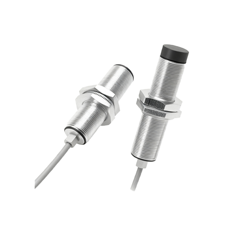
Core Components of a Proximity Sensor Circuit
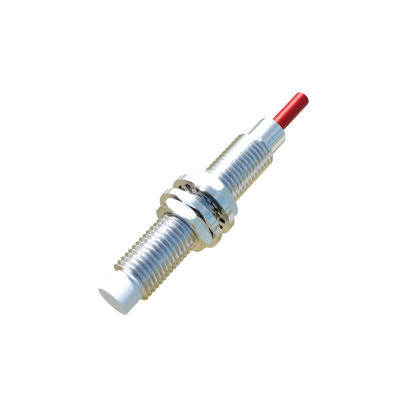
A functional proximity sensor circuit extends beyond the sensing element itself. It integrates several key components to ensure stable operation and interface compatibility with control systems like PLCs (Programmable Logic Controllers). The primary components include the oscillator circuit, which generates the high-frequency electromagnetic field in inductive sensors. The detection circuit monitors changes in the oscillator's amplitude or frequency caused by a target. Following this, a signal conditioning circuit, comprising amplifiers and filters, processes the weak detection signal. A Schmitt trigger is then typically employed to convert the analog signal into a clean, digital on/off output, providing hysteresis to prevent output chatter. Finally, the output stage delivers the switching signal. This can be a transistor output (NPN sinking or PNP sourcing) for DC sensors or a solid-state relay for AC variants. Protection elements like reverse polarity protection diodes, surge suppressors, and current-limiting resistors are critical for industrial durability.
Detailed Inductive Proximity Sensor Schematic Analysis
Examining a standard 3-wire DC inductive proximity sensor schematic provides practical insight. The circuit operates on a supply voltage, typically 10-30V DC. The core is an LC-tank oscillator circuit, where the sensor's face acts as the inductor (L). A detection coil is coupled to this oscillator. In the absence of a metal target, the oscillator runs at high amplitude. When a metal target enters the field, eddy currents are induced in the target, loading the oscillator and reducing its amplitude. This amplitude drop is detected and amplified. The amplified signal drives a comparator with hysteresis (Schmitt trigger), which switches state cleanly. The output transistor (e.g., an NPN type) is controlled by this trigger. In an NPN configuration, the output wire acts as a switch to ground (0V). When active, it sinks current from the load (like a PLC input) connected to the positive supply. A clamping diode across the output protects against voltage transients from inductive loads. The brown wire is typically +V, blue is 0V/common, and black is the switched output signal.
Interfacing with Control Systems and Loads
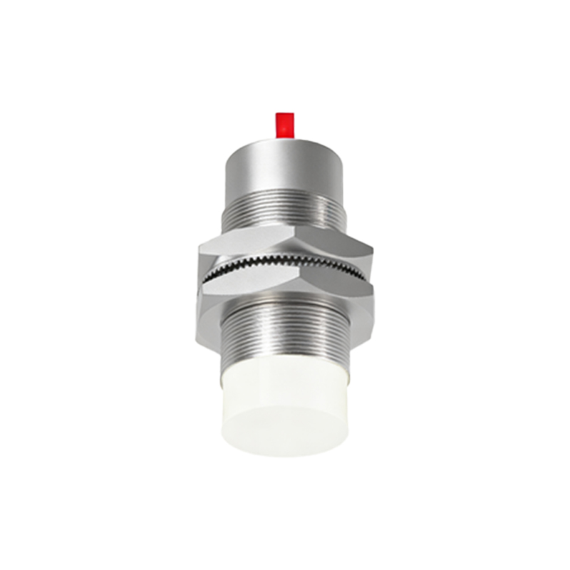
The ultimate purpose of the sensor circuit is to reliably interface with an industrial control system. For DC sensors, understanding the sinking (NPN) and sourcing (PNP) paradigms is crucial. A sinking (NPN) sensor switches the negative side of the load; the load is connected between the positive supply and the sensor's output wire. A sourcing (PNP) sensor switches the positive side. The choice must match the PLC input module type. For direct connection to relays or small actuators, the sensor's output current and voltage ratings must not be exceeded. A common interface circuit involves connecting the sensor output to a PLC digital input module. The module's internal circuitry, often including an opto-isolator, completes the circuit. For long cable runs in electrically noisy environments, using shielded cables with proper grounding at the controller end is essential to prevent false triggering. Additionally, placing a snubber circuit or flyback diode across inductive loads (relays, solenoids) driven by the sensor is recommended to suppress voltage spikes.
Design Considerations for Reliability and Safety
Robust circuit design is paramount in industrial settings. Key considerations include environmental factors such as temperature ranges, which affect oscillator stability and component ratings. Electrical noise immunity is enhanced by incorporating filtering in the signal conditioning stage and using twisted-pair or shielded cabling. Short-circuit and overload protection on the output transistor prevents damage from wiring errors. For capacitive sensors, sensitivity adjustment circuits are necessary to compensate for different target materials and to ignore background objects. Mounting and housing design also play an electrical role; metallic flush-mount sensors require a specific "shielded" design to prevent side-sensing, while non-flush models have a longer range. Always adhere to relevant safety standards (e.g., IEC 60947-5