Introduction to Proximity Switch Sensor Safety Barriers
In the realm of industrial automation, proximity switches are indispensable components for non-contact detection of objects. These sensors, whether inductive, capacitive, or photoelectric, are often deployed in hazardous areas where flammable gases, vapors, or dust may be present. The intrinsic safety (IS) of such electrical circuits is paramount to prevent ignition. This is where safety barriers, also known as intrinsic safety barriers or isolators, become critical. A safety barrier is a passive network device installed between the safe area (control system) and the hazardous area (field device like a proximity sensor). Its primary function is to limit the energy—voltage and current—transmitted to the hazardous area to levels below what is required to ignite a specific hazardous atmosphere, thereby ensuring operational safety even under fault conditions.
Core Principles and Functionality
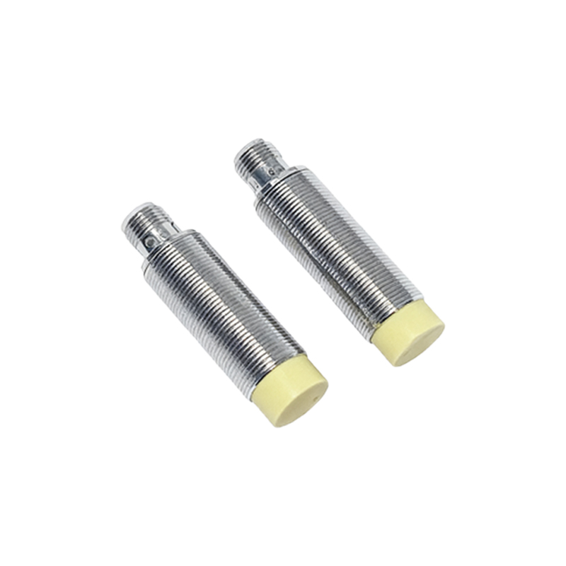
The fundamental principle of a safety barrier is energy limitation. It acts as a protective gate. Under normal operating conditions, the barrier allows the signal from the proximity sensor (e.g., a switching signal) to pass through to the control system with minimal interference. It typically consists of current-limiting resistors, voltage-limiting Zener diodes, and fast-acting fuses. In the event of a fault in the safe-area equipment—such as a dangerous voltage surge—the Zener diodes clamp the voltage to a safe level, while the resistors limit the current. If the fault current exceeds a safe threshold, the fuse blows, permanently and safely disconnecting the hazardous-area circuit. This design ensures that the energy in the circuit connected to the proximity switch in the hazardous zone never exceeds the ignition energy of the surrounding atmosphere.
Key Selection Criteria for Safety Barriers
Selecting the correct safety barrier for a proximity switch application is not a trivial task. Engineers must consider several crucial parameters. First is the sensor type and its electrical characteristics: the barrier must be compatible with the sensor's operating voltage, current consumption, and signal type (e.g., NAMUR proximity sensors are specifically designed for use with safety barriers). Second, the entity parameters—Um (maximum input voltage), Ui (maximum input voltage for intrinsic safety), Ii (maximum input current), Pi (maximum input power), Ci, and Li (internal capacitance and inductance)—of the barrier must be carefully matched with the entity parameters of the field device (the proximity switch) and the cable parameters. This "entity concept" ensures that the system remains intrinsically safe. Third, the hazardous area classification (Zone 0, 1, or 2 for gas; Zone 20, 21, or 22 for dust) and the required temperature class (T1 to T6) dictate the barrier's certification (e.g., ATEX, IECEx, UL).
Integration with Different Proximity Sensor Types
The integration methodology varies slightly depending on the proximity sensor technology. For two-wire DC inductive or capacitive proximity switches, a standard DC switch input safety barrier is used. It supplies the necessary operating voltage to the sensor and transmits the switching signal back. For three-wire sensors, which have separate power and signal lines, appropriate barriers for both the power supply and the signal line are required. NAMUR sensors are a special case; they are two-wire sensors that require a specific evaluation circuit, often integrated into a dedicated NAMUR input safety barrier or an isolated barrier. This setup provides a distinct advantage: the sensor itself operates at very low power (typically<1V,<10mA), making it inherently safe, and the barrier provides the interface to the higher-voltage control system.
Installation, Wiring, and Maintenance Best Practices
Proper installation is critical for maintaining the integrity of the intrinsic safety system. Safety barriers must be mounted in a certified enclosure within the safe area. A fundamental rule is the strict physical separation of intrinsically safe (IS) and non-intrinsically safe (Non-IS) wiring. IS cables (blue in many standards) should be routed separately from Non-IS cables, preferably in separate cable trays or conduits, to prevent energy coupling. Grounding is another vital aspect; the ground terminal of the safety barrier must be connected to a high-integrity, dedicated earth ground with low impedance to ensure effective voltage clamping during faults. During maintenance, it is essential to verify that any replacement barrier has the exact same certification and entity parameters as the original. Regular inspections should check for loose connections, corrosion, and integrity of the grounding system.
Benefits and Impact on System Reliability
Implementing safety barriers for proximity switches delivers significant benefits beyond mere regulatory compliance. The foremost benefit is enhanced personnel and asset safety, drastically reducing the risk of explosions in hazardous locations. Furthermore, because