Understanding the Normal Blink Pattern
A common indicator of a functioning photoelectric sensor is its status LED, which typically blinks or changes color to signal operational states like power-on, object detection, or alignment. This visual feedback is crucial for setup and diagnostics. The specific blink pattern—such as a steady blink for power, a faster blink for a received signal, or a solid light for a detected object—varies by manufacturer and model. Understanding this expected behavior from the sensor's datasheet is the first step in identifying an anomaly. When the LED stops blinking entirely, remains solidly lit, or is completely dark, it indicates a deviation from normal operation that requires investigation.
Primary Causes for a Non-Blinking LED
Several core issues can lead to a photoelectric sensor's indicator LED not blinking as expected. The most fundamental cause is a power supply problem. This includes incorrect voltage (e.g., applying 24VDC to a 12VDC sensor), reversed polarity, or insufficient current capacity from the power source. A complete lack of power will result in no light at all. Another major category is wiring faults. Loose connections, broken wires, or short circuits in the cable or at the terminal block can interrupt power or signal communication. Environmental factors also play a significant role. Excessive accumulation of dust, dirt, or moisture on the sensor's lens can block the light beam, potentially causing the output to latch and the LED to remain in a constant state. Finally, internal component failure, though less common, can occur due to electrical surges, physical damage, or prolonged operation in harsh conditions beyond its specifications.
Step-by-Step Troubleshooting Procedure
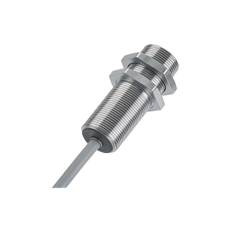
A systematic approach is essential for efficient troubleshooting. Begin by verifying the power supply. Use a multimeter to confirm that the correct voltage is present at the sensor's terminals. Ensure the power supply is adequately rated for the sensor's current draw, especially if multiple devices are connected. Next, inspect all physical connections. Check for tight terminal screws, examine the cable for pinch points or cuts, and verify the wiring diagram against your connections, paying close attention to the sink/source (NPN/PNP) configuration relative to your PLC input. Proceed by cleaning the sensor's lens and reflector (if applicable) with a soft, lint-free cloth. For opposed (through-beam) sensors, ensure the emitter and receiver are perfectly aligned; a misalignment tool can be helpful. If possible, test the sensor with a known-good object in its optimal sensing range, away from highly reflective or absorbent backgrounds that might interfere.
Advanced Diagnostics and Configuration Checks
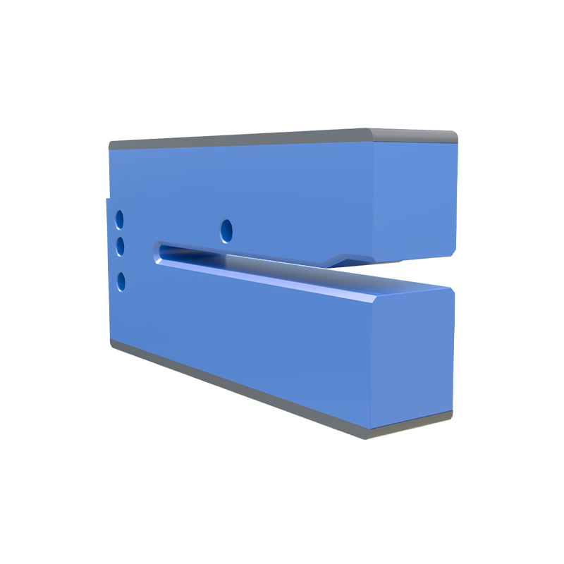
If basic checks yield no results, delve into configuration and signal monitoring. Many modern photoelectric sensors have teach-in functions or configurable operating modes (light-on/dark-on). Accidentally changing this mode can make the sensor behave counter-intuitively. Consult the manual to perform a reset or re-teach the sensing threshold. Use an oscilloscope or a PLC input monitor to check the sensor's output signal directly. The absence of a switching signal despite a correct power supply points to an internal fault. For sensors with built-in diagnostics or IO-Link capability, connect to the manufacturer's software to read detailed status information, error codes, and signal strength, which can pinpoint issues like marginal signal levels or internal errors.
Preventive Measures and Best Practices
Preventing issues is more efficient than troubleshooting them. Start by selecting the right sensor for the application, considering factors like sensing range, response time, housing material (IP rating), and light source (red light, laser, infrared) suitable for the target object and environment. Ensure proper installation: use mounting brackets to minimize vibration, route cables away from high-voltage lines to prevent electrical noise, and install protective guards or air blowers if dust accumulation is rapid. Implement a regular maintenance schedule to clean lenses and check connections. For critical applications, consider installing a sensor with a dual digital output or an analog output that provides continuous feedback on signal strength, allowing for predictive maintenance before a complete failure occurs.