Understanding Proximity Sensor Types and Their Electrical Characteristics
Proximity sensors are essential components in industrial automation, detecting the presence or absence of objects without physical contact. The two primary categories are inductive and capacitive sensors. Inductive sensors are used for detecting metallic objects, operating on the principle of electromagnetic induction. They generate an oscillating electromagnetic field, and when a metal target enters this field, it causes a change in oscillation amplitude, triggering the sensor output. Capacitive sensors, on the other hand, can detect both metallic and non-metallic materials by sensing changes in capacitance. Understanding these types is crucial before proceeding with wiring, as their electrical characteristics, such as operating voltage, output type (PNP or NPN), and current ratings, directly influence the wiring configuration.
Key Components of a Standard Proximity Sensor Wiring Diagram
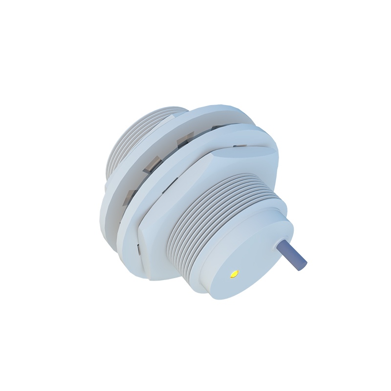
A typical proximity sensor wiring diagram includes several key components: the sensor itself, a power supply, a load (such as a PLC input, relay, or indicator lamp), and connecting wires. The sensor usually has three or four wires: brown (or red) for positive DC supply, blue for negative DC supply (common ground), black (or white) for the output signal, and sometimes a white wire for a complementary output or shield. The power supply must match the sensor's voltage rating, commonly 10-30V DC. The load is connected between the output wire and either the positive or negative supply, depending on whether the sensor is PNP (sourcing) or NPN (sinking). Proper identification of these components ensures a safe and functional connection.
Step-by-Step Wiring Procedure for PNP and NPN Sensors
Wiring a proximity sensor correctly requires attention to the output type. For a PNP (sourcing) sensor, the output switches the positive voltage. Connect the brown wire to the positive terminal of the power supply and the blue wire to the negative terminal. Then, connect the black output wire to one terminal of the load, and the other terminal of the load to the negative supply. When the sensor detects an object, it sources current to the load. For an NPN (sinking) sensor, the output switches the negative side. Wire the brown and blue wires similarly, but connect the black output wire to one load terminal and the other load terminal to the positive supply. Here, the sensor sinks current from the load to ground upon detection. Always verify the sensor's datasheet for specific wire color codes and ratings.
Common Wiring Configurations: 2-Wire, 3-Wire, and 4-Wire Sensors
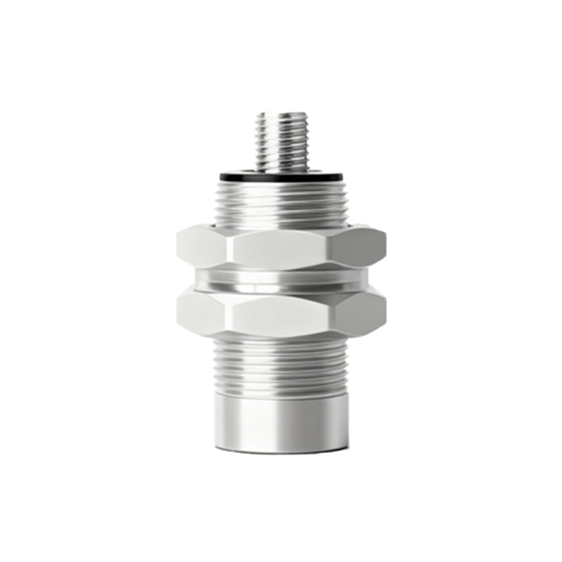
Proximity sensors come in different wire configurations. Two-wire sensors are simple, with one wire for power and the other for load connection, but they may have higher leakage current. Three-wire sensors are the most common, offering separate power and output wires for better performance and lower leakage. Four-wire sensors typically provide two complementary outputs (e.g., normally open and normally closed) or include a shield wire for noise reduction in electrically noisy environments. When wiring, ensure that the load current does not exceed the sensor's maximum switching capacity. For AC sensors, additional considerations like load compatibility and voltage ratings apply, though DC sensors are more prevalent in modern systems.
Best Practices for Installation and Troubleshooting
Proper installation extends sensor life and reliability. Mount the sensor securely, ensuring the sensing face is unobstructed and aligned correctly with the target. Maintain adequate clearance from metal surfaces to prevent false triggering. Use shielded cables in areas with high electromagnetic interference and ground the shield at one end only. For troubleshooting, start by checking the power supply voltage with a multimeter. Verify connections against the wiring diagram, and inspect for loose wires or short circuits. If the sensor fails to trigger, test it by bringing a target within the specified sensing range. Regular maintenance, including cleaning the sensing face and checking for environmental damage, helps prevent unexpected downtime.
Safety Precautions and Compliance with Industry Standards
Safety is paramount when working with electrical systems. Always disconnect power before wiring or modifying connections. Use tools with insulated handles and wear appropriate personal protective equipment. Ensure that the sensor and wiring comply with relevant industry standards, such as IEC 60947-5-2 for proximity sensors, which covers performance and safety requirements. Implement proper circuit protection, such as fuses or circuit breakers, to prevent overcurrent damage. Additionally, consider environmental factors like temperature, humidity, and chemical exposure, selecting sensors with suitable ingress protection (IP) ratings. Adhering to these guidelines minimizes risks and ensures operational integrity in industrial settings.