Introduction to Photoelectric Sensors in Stamping
Photoelectric sensors are critical components in modern industrial safety systems, particularly within stamping and pressing operations. These devices utilize light beams to detect the presence or absence of objects, ensuring that machinery operates only when it is safe to do so. In high-risk environments like stamping presses, where heavy mechanical forces are applied rapidly, the integration of photoelectric sensors forms a fundamental part of machine guarding strategies. By creating an invisible safety curtain or light barrier around hazardous zones, these sensors can instantly halt machine motion if an operator's hand, tool, or any other object breaches the protected area. This immediate response is vital for preventing severe injuries, such as crushing or amputation, making photoelectric sensors a non-negotiable element in industrial safety compliance and risk management protocols. Their reliability, speed, and non-contact nature offer distinct advantages over traditional mechanical guards or two-hand control systems.
Core Operating Principles and Technology
The fundamental principle behind a photoelectric safety sensor is based on the emission, transmission, and reception of light. Typically, these systems consist of a transmitter unit that projects a modulated infrared light beam and a separate receiver unit designed to detect this specific light signal. The light is often pulsed at a high frequency with a unique coded pattern. This coding is crucial as it makes the system immune to interference from ambient light sources, such as factory lighting or sunlight, ensuring high reliability. The receiver continuously monitors the integrity of the received light signal. When an object interrupts the beam, the receiver detects the break in the signal pattern. Within milliseconds, this event triggers a safety-rated output signal that commands the stamping press's control system to initiate a protective stop, typically by engaging the brake and removing power to the dangerous motion. The system's design ensures a fail-safe operation; any failure within the sensor electronics, a severed cable, or a dirty lens that blocks light will also cause a safety shutdown, maintaining protection integrity.
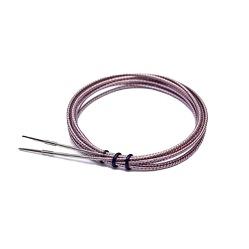
Key Configurations: Through-Beam and Retroreflective
Two primary configurations are employed in stamping applications: through-beam (or opposed) and retroreflective systems. In a through-beam setup, the transmitter and receiver are installed in separate housings, facing each other directly across the hazard zone. This arrangement creates a single, highly precise beam. It offers the longest sensing ranges and highest accuracy, making it suitable for protecting large press openings or perimeter guarding. The retroreflective configuration uses a single housing containing both the emitter and receiver, along with a specialized reflector (a retroreflector) placed opposite. The emitter sends light to the reflector, which bounces it directly back to the receiver. This setup simplifies wiring and alignment since only one device needs to be connected to the control system. However, its sensing range is generally shorter than that of a through-beam system. For both types, multiple units can be aligned to create a vertical array or "light curtain," providing a full-height protective screen in front of a stamping press.
Integration with Machine Control and Safety Standards
For a photoelectric sensor system to be effective, its integration with the stamping press's control system is paramount. The sensor's output is connected to a safety relay or a dedicated safety controller. This device is responsible for processing the stop signal and executing the shutdown command in a reliable, monitored manner. The entire safety circuit, including the sensors, wiring, and the final switching elements controlling the press motor or brake, must be designed to meet stringent international safety standards. Key standards include ISO 13849-1, which defines Performance Levels (PL), and IEC 62061, which defines Safety Integrity Levels (SIL). For stamping presses, systems typically require a minimum performance level of PL d or SIL 2. This involves using redundant circuits, self-checking mechanisms, and monitored outputs to ensure that no single fault can lead to a loss of the safety function. Regular validation testing, as mandated by these standards, is also critical to ensure ongoing system integrity.
Advantages Over Traditional Guarding Methods
Photoelectric safety sensors offer significant operational and safety advantages compared to traditional physical guards. Fixed physical guards can hinder material loading, tool changeovers, and maintenance, often leading to their temporary removal and creating exposure to risk. In contrast, light curtains provide unobstructed access to the machine for feeding materials while maintaining continuous protection. They allow for faster production cycles since operators do not need to open and close physical gates. Furthermore, their flexibility is a major benefit; the protected area can be easily adjusted or the system moved to guard different machines, adapting to changing production layouts. The non-contact sensing eliminates wear and tear associated with mechanical switches or gates. Most importantly, the reaction time of a photoelectric system is extremely fast, often in the range of 10-20 milliseconds, providing a higher level of personnel protection by stopping the machine before a hazardous motion can complete its cycle.
Installation, Alignment, and Maintenance Best Practices
Correct installation and alignment are critical for the reliable operation of photoelectric safety systems. The sensors must be mounted on stable, vibration-resistant surfaces to prevent misalignment. For through-beam systems, precise optical alignment between the transmitter and receiver is essential; even a slight misalignment can attenuate the light signal, potentially causing nuisance trips or, worse, a failure to detect an intrusion. Retroreflective systems require careful alignment with the reflector. During installation, a built-in alignment aid, such as an LED indicator showing signal strength, is invaluable. Regular maintenance is a mandatory part of safety protocol. This includes periodic cleaning of lenses and reflectors to prevent dust, oil mist, or debris from attenuating the light beam. Functional testing should be performed at the start of each shift or in accordance with the manufacturer's and safety standard's requirements, verifying that the system correctly initiates a safety stop when the beam is blocked. Any fault indicated by the system's diagnostics must be investigated and resolved immediately before operations resume.
Future Trends and Technological Advancements
The technology behind safety photoelectric sensors continues to evolve, driven by the demands of Industry 4.0 and smart manufacturing. Modern sensors now feature enhanced diagnostics and connectivity, communicating status information directly to plant networks or supervisory systems for predictive maintenance. This allows issues like gradual lens contamination or early signs of component degradation to be flagged before they cause a failure. Another trend is the development of multi-beam systems with higher resolution, capable of differentiating between a small tool and a human body part, allowing for more sophisticated muting and blanking functions. These functions can temporarily disable specific sections of the light curtain to allow for the automated passage of materials without compromising overall safety. Furthermore, the integration of vision-based safety systems, which use cameras and image processing to monitor complex hazard zones, is emerging as a complementary technology, offering new possibilities for safeguarding intricate stamping and robotic cell operations.