Introduction to the APS4-12S Proximity Sensor
The APS4-12S is a widely adopted inductive proximity sensor designed for robust industrial automation tasks. Characterized by its compact cylindrical M12 housing, this sensor offers reliable non-contact detection of metallic objects. Its three-wire configuration is standard for modern DC sensors, providing a balance of performance, safety, and ease of integration. Understanding the correct wiring procedure is fundamental to ensuring optimal sensor operation, preventing damage to the sensor or the connected controller, and maintaining system uptime in demanding environments such as assembly lines, packaging machinery, and material handling systems.
Understanding the Three-Wire DC System
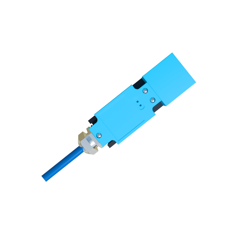
Unlike two-wire sensors that operate in series with the load, three-wire sensors like the APS4-12S have dedicated power and load connections. This design offers superior performance with lower leakage current and faster switching speeds. The system operates on a DC power supply, typically 10-30V DC. The three wires are color-coded according to international standards: brown for positive supply voltage (+V), blue for common negative or ground (0V), and black for the output signal (LOAD). It is critical to verify the specific manufacturer's datasheet, as some regional variations or specific models might differ, but the brown/blue/black scheme is predominant for DC sensors.

Detailed Wiring Procedure and Connections
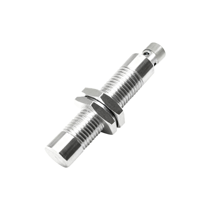
Proper wiring begins with a safe lock-out/tag-out procedure to isolate the electrical panel. First, connect the blue wire to the DC power supply's negative terminal (0V). Second, connect the brown wire to the DC power supply's positive terminal (+V), ensuring the voltage is within the 10-30V DC range. The third wire, black, is the output. For an NPN (sinking) output sensor, the black wire connects to the load (e.g., a PLC input module), and the other side of that load is connected to the positive supply (+V). For a PNP (sourcing) output version, the black wire still connects to the load, but the other side of the load is connected to the negative supply (0V). Always confirm whether your APS4-12S model is NPN or PNP before making final connections.
Integrating with a Programmable Logic Controller (PLC)
Integration with a PLC is a common application. For a PNP sensor connected to a PLC digital input card, wire the brown to +24V DC, blue to 0V, and the black output wire to the specific PLC input terminal. The PLC input card's common must be connected to 0V. For an NPN sensor, the wiring changes: brown to +24V, blue to 0V, and black to the PLC input. However, the PLC input card's common must now be connected to +24V DC to complete the circuit. Incorrect common connection is a primary cause of sensor malfunction in PLC systems. Always use shielded cable for longer runs and ground the shield at the controller end to minimize electrical noise interference.
Critical Considerations for Reliable Operation
Several factors are crucial for long-term reliability. Ensure the sensor is properly mounted with the correct sensing distance and free from mutual interference with other sensors. The load current of the connected device must not exceed the sensor's maximum switching capacity, typically 200mA for the APS4-12S. Incorporate a protective circuit such as a fuse or circuit breaker on the supply line. For inductive loads like relays or solenoids, connect a flyback diode or surge absorber in parallel with the load to suppress voltage spikes that can damage the sensor's internal switching transistor. Regularly inspect wiring for abrasion, corrosion, or loose terminals.
Troubleshooting Common Wiring Issues
If the sensor fails to operate, a systematic approach is needed. First, verify power is present between the brown and blue wires using a multimeter. Next, check the output. Actuate the sensor by placing a metal target within its sensing range. Measure the voltage between the black and blue wires (for PNP) or black and brown wires (for NPN). A significant voltage change should be observed. If power is correct but the output does not switch, the sensor may be faulty or the load may be excessive. If the output switches but the PLC does not register it, verify the PLC common connection and input point configuration. Consistently incorrect operation often points to a wiring error between the sensor type (NPN/PNP) and the controller's input circuit.
Conclusion and Best Practices
Correctly wiring the APS4-12S three-wire proximity sensor is a straightforward yet vital task.