Introduction to Photoelectric Speed Sensing
Photoelectric sensors have become a cornerstone technology for non-contact rotational speed measurement across diverse industrial sectors. These devices operate on a fundamental principle: they detect changes in light intensity caused by a rotating object, converting these optical interruptions into precise electrical signals. The core system typically comprises a light source, such as an LED or laser diode, a photodetector (phototransistor or photodiode), and a signal processing unit. As a reflective or slotted disc attached to the rotating shaft passes through the sensor's field, it modulates the light beam. This modulation generates a pulsed output signal whose frequency is directly proportional to the rotational speed. The inherent advantages of this method, including high accuracy, excellent resolution, and minimal mechanical wear, make it superior to traditional contact methods like tachometers for many demanding applications.
Core System Components and Configurations
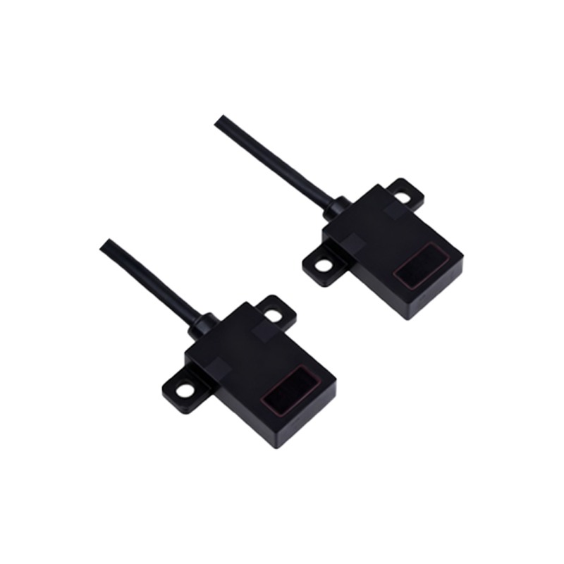
The effectiveness of a photoelectric tachometry system hinges on its components. Common configurations include the through-beam (opposed) type, where the emitter and receiver are housed in separate units facing each other, offering the longest sensing range and highest reliability. The retro-reflective type uses a single housing containing both elements and a reflector, simplifying alignment. Diffuse (proximity) sensors detect light reflected directly from the target itself. For rotational speed, the through-beam or retro-reflective types are often paired with an encoder disk. This disk features alternating transparent and opaque segments; the number of pulses per revolution (PPR) is determined by the number of segments. A higher PPR count yields greater measurement resolution. The choice of light source wavelength (e.g., infrared, red, or laser) is critical for overcoming environmental challenges like ambient light interference or target material properties.
Signal Processing and Data Acquisition
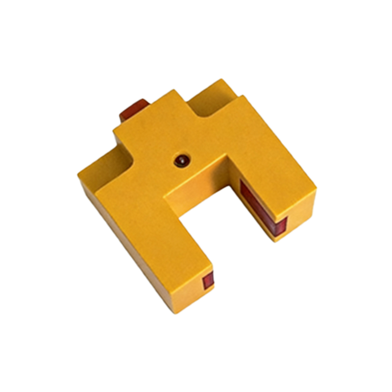
The raw pulsed signal from the photodetector requires conditioning to become a usable speed reading. Initial amplification is often necessary. Subsequent stages involve filtering to remove electrical noise and shaping to produce clean, digital square waves. A microcontroller or dedicated frequency-to-voltage converter then processes this signal. The primary calculation is straightforward: Rotational Speed (RPM) = (Frequency in Hz * 60) / (Number of Pulses per Revolution). Advanced systems implement digital signal processing (DSP) algorithms to enhance accuracy in noisy environments or at very low speeds. For variable speed applications, the response time of the sensor and processor is paramount to ensure real-time feedback. Data can be displayed locally, transmitted via industrial protocols (4-20mA, 0-10V, or digital buses like IO-Link), or integrated into a larger control system for monitoring and closed-loop control.
Key Advantages Over Alternative Methods
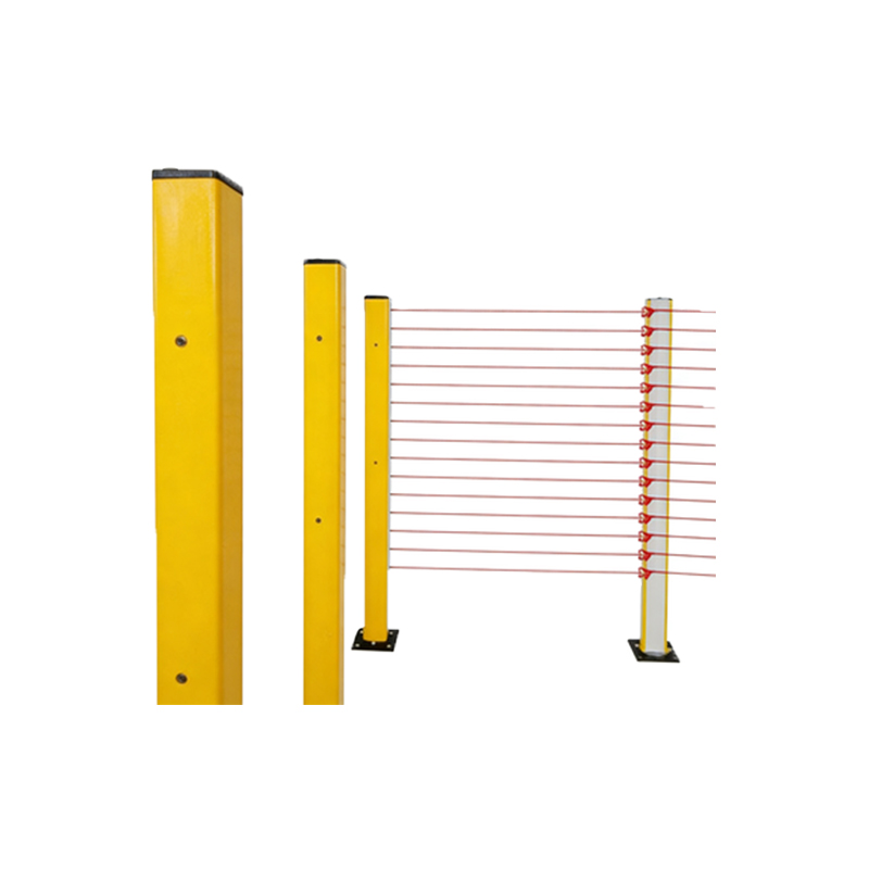
Photoelectric sensors offer distinct benefits that solidify their role in modern industry. Their non-contact nature eliminates frictional losses and prevents wear on both the sensor and the measured shaft, ensuring long-term reliability and maintenance-free operation. They are capable of measuring extremely high rotational speeds where physical contact would be impossible or dangerous. The technology provides exceptional accuracy and repeatability, often within ±0.05% of the reading, which is vital for precision manufacturing and quality control. Furthermore, these sensors are highly versatile, capable of measuring speed on various materials (metal, plastic, paper) and in diverse environmental conditions when properly housed. Their digital output seamlessly integrates with programmable logic controllers (PLCs) and data acquisition systems.
Practical Application Considerations and Challenges
Successful implementation requires careful consideration of several factors. Proper mounting and alignment are critical to ensure consistent beam interruption. The selection of the encoder disk's PPR must balance resolution needs with the maximum frequency the sensor and controller can handle. Environmental contaminants like dust, oil mist, or steam can attenuate the light beam, necessitating sensors with high ingress protection (IP) ratings or modulated light signals to reject ambient light. Vibration can cause misalignment. For very low-speed measurements, the system must be sensitive enough to detect slow passage of segments. In such cases, specialized sensors with background suppression or contrast-based detection are employed. Regular maintenance, primarily lens cleaning, is essential to sustain optimal performance.
Industry Applications and Future Trends
Applications are ubiquitous. In automotive manufacturing, they monitor the speed of assembly line conveyors, robotic arms, and engine test stands. Within the aerospace sector, they are used in turbine and auxiliary power unit testing. They are fundamental in packaging machinery for synchronizing operations and in printing presses for registration control. The renewable energy sector relies on them for monitoring wind turbine rotor speeds. Future trends point towards increased miniaturization, the integration of intelligent features like self-diagnostics and condition monitoring via IO-Link, and enhanced robustness for extreme environments. The convergence of photoelectric sensing with Industrial Internet of Things (IIoT) platforms will enable predictive maintenance, where speed data trends predict bearing wear or imbalance before failure occurs.