Understanding the Computer Optical Sensor
Before beginning the installation process, it is crucial to understand the component you are working with. A computer optical sensor, often found in devices like optical mice, barcode readers, or certain security systems, is a device that detects light, typically from an LED or laser, and converts it into an electrical signal. The core principle involves capturing reflected light to track movement or read encoded data. For installation, you must first identify the specific type of sensor—whether it's a surface-mount device (SMD) for PCB integration, a through-hole component, or a pre-assembled module with a USB or other interface. Consult the manufacturer's datasheet for critical specifications such as operating voltage, current requirements, signal output type (digital or analog), and the pinout configuration. This preliminary step ensures compatibility with your host system and prevents potential damage from incorrect power supply or connection.
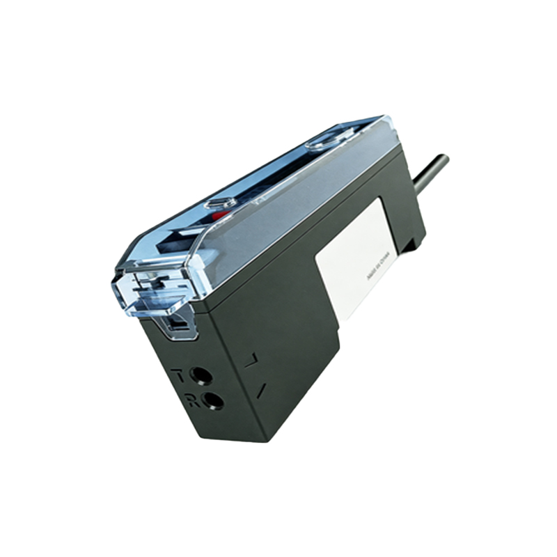
Gathering Necessary Tools and Materials
Professional installation demands the right tools and a static-safe workspace. Essential tools include a precision screwdriver set, needle-nose pliers, a soldering iron with a fine tip (for non-modular sensors), high-quality solder, and a desoldering pump or wick if replacing an existing component. For modular USB sensors, no soldering may be required. You will also need the optical sensor itself, its connecting cable (if applicable), and the host device or PCB. Crucially, employ an anti-static wrist strap connected to a grounded point throughout the procedure to prevent electrostatic discharge (ESD) from damaging the sensitive semiconductor elements within the sensor. Ensure your workspace is well-lit, clean, and free from dust, which can interfere with the sensor's optical path post-installation.
Pre-Installation Safety and Preparation
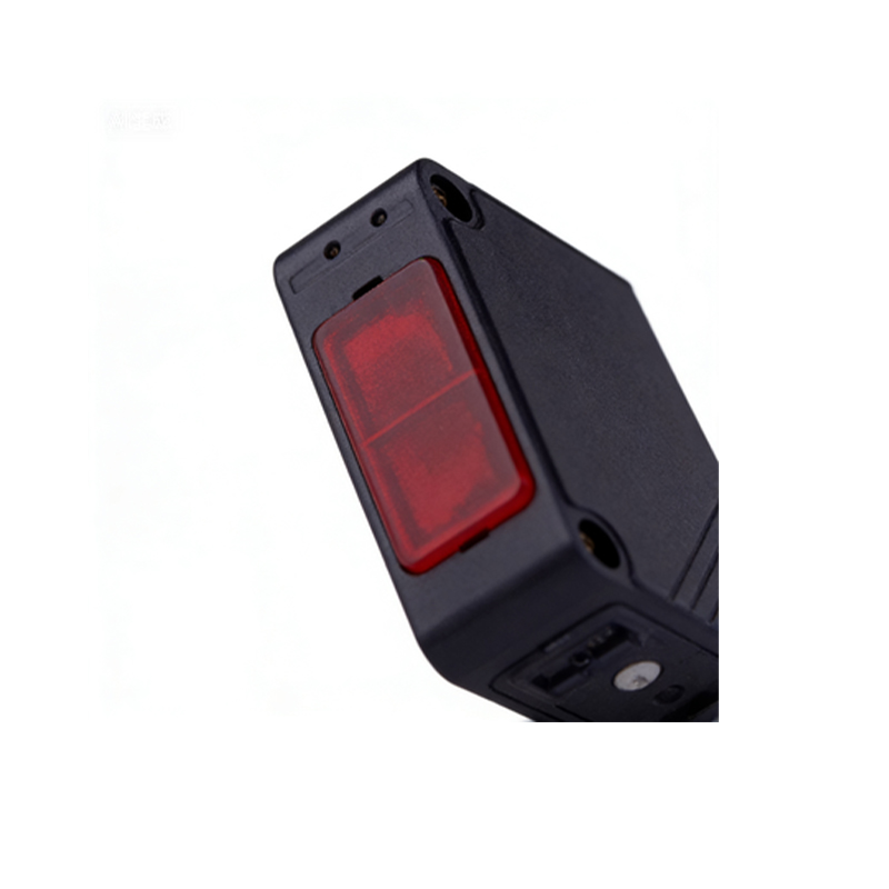
Safety is paramount. Power down the computer or host device completely and disconnect it from all power sources, including batteries. If working on an internal PCB, remove it from the chassis if necessary to provide clear access. For through-hole or SMD sensors on a PCB, inspect the board for any existing damage or residue. Clean the contact pads or holes using isopropyl alcohol and a lint-free swab to ensure a good electrical connection. If you are replacing an old sensor, carefully desolder it, taking care not to overheat the surrounding components or lift the PCB pads. Double-check the orientation of the new sensor. Most optical sensors have a marked pin 1 (indicated by a dot, notch, or beveled edge) that must align with the corresponding marking on the PCB silkscreen. Incorrect orientation will render the sensor non-functional.
Physical Installation and Mounting
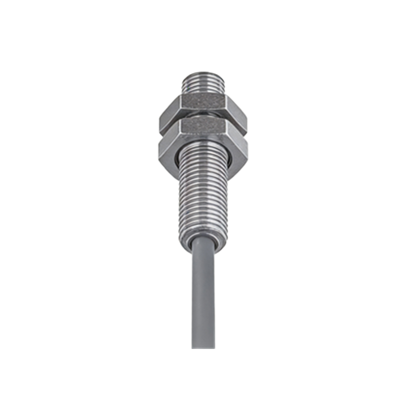
The mounting method depends on the sensor type. For a through-hole component, insert the sensor's leads into the correct PCB holes, ensuring it sits flush against the board. On the opposite side of the board, bend the leads slightly to hold it in place temporarily. For SMD sensors, use tweezers to position the component accurately over its footprint. A small amount of solder paste applied to the pads can help secure it before the main soldering step. For external modular sensors (e.g., an optical mouse sensor), the process involves mechanical fitting. Open the device housing according to the manufacturer's disassembly guide. Align the sensor module with its mounting points or bracket, and secure it using the provided screws or clips. Ensure the sensor's lens is clean and unobstructed, and that it is positioned at the correct focal distance from the surface it will read, as specified in the documentation.
Electrical Connection and Soldering
This is the most critical technical phase. For soldered connections, apply the soldering iron tip to both the pad and the component lead simultaneously, then feed a small amount of solder to form a clean, concave fillet. Avoid solder bridges between adjacent pins, especially on fine-pitch SMD sensors. Use a magnifying glass or microscope to inspect each joint for quality. For multi-pin sensors, follow the pinout diagram meticulously. Typical connections include VCC (power supply, e.g., +5V), GND (ground), and signal output lines. If the sensor has an integrated LED, it may have separate anode and cathode pins. After soldering, use a multimeter in continuity mode to check for short circuits between power and ground pins. For plug-and-play modules, simply connect the interface cable (e.g., USB, PS/2) to the corresponding port on the computer, ensuring a firm connection.
Software Configuration and Driver Installation
Once the hardware is installed, power on the system. The operating system may automatically detect a new USB human interface device (HID) like a mouse. However, for specialized or industrial optical sensors, you will likely need to install specific drivers or configuration software provided by the manufacturer. Download the latest drivers from the official website. During installation, follow the on-screen prompts. For sensors integrated into a custom system, you may need to configure settings within the device's firmware or application software. This could involve calibrating the sensor's sensitivity, setting the sampling rate, or defining its operational mode. Verify that the sensor appears correctly in the system's device manager without any warning symbols, indicating a properly recognized device.
Functional Testing and Calibration
After installation and software setup, comprehensive testing is essential. For a pointing device sensor, move the mouse over various surfaces to check for smooth, accurate cursor response without jitter or skipping. For a barcode reader, scan test codes to verify accurate data capture. Use the provided software utilities to monitor the raw data output or signal quality. Check for consistent operation without intermittent dropouts. If the sensor includes adjustable parameters like lift-off distance or resolution, perform calibration as per the manual. This often involves running a calibration routine on a standard test surface. Additionally, test the sensor under different lighting conditions if it is designed for ambient light immunity. Any malfunction at this stage requires re-checking physical alignment, solder joints, and software settings.
Troubleshooting Common Installation Issues
Even with careful installation, issues may arise. If the sensor is completely unresponsive, re-verify power and ground connections with a multimeter. Ensure the voltage at the VCC pin matches the datasheet requirement. Intermittent operation often points to a poor solder joint or a loose cable connection; reflow suspicious solder points. If the sensor is detected but provides erratic or incorrect data, suspect optical obstruction—clean the lens meticulously. Incorrect output can also stem from software/driver conflicts; try the sensor on a different system port or computer. For noise-related issues, ensure the sensor's signal lines are not routed near sources of electromagnetic interference. Consulting the manufacturer's application notes or support forum for known issues with your specific model is always a recommended step in professional troubleshooting.