Introduction to Proximity Sensor Motors
A proximity sensor motor represents a sophisticated integration of sensing technology and electromechanical actuation. At its core, this system combines a proximity sensor—a device capable of detecting the presence or absence of nearby objects without physical contact—with an electric motor, which provides the necessary mechanical motion. The synergy between these two components enables highly automated, precise, and reliable operations across a vast spectrum of industrial applications. From automated assembly lines and robotic arms to conveyor systems and safety interlocks, proximity sensor motors are fundamental to modern manufacturing and process control. This article delves into the intricate working principles that govern these systems, exploring the types of sensors involved, the control mechanisms, and the resulting motor actions.
Core Working Principle: The Sensing Element
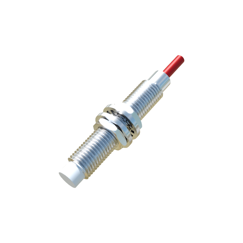
The operation begins with the proximity sensor itself. These sensors function based on various physical principles, primarily electromagnetic, capacitive, or optical. Inductive proximity sensors, most common in metal-detection applications with motors, generate an oscillating electromagnetic field. When a metallic target enters this field, eddy currents are induced in the target, causing a change in the sensor's oscillation amplitude. This change is detected by the sensor's internal circuitry. Capacitive sensors can detect both metallic and non-metallic objects by measuring changes in capacitance. Optical sensors use a light emitter and receiver to detect object presence. The key outcome is the same: the sensor produces a discrete electrical signal, typically a switch from a high to a low voltage state (or vice-versa), indicating the detection of an object within its preset sensing range.
Signal Processing and Control Logic
The raw signal from the proximity sensor is rarely used directly to drive a motor. It first travels to a control unit, such as a Programmable Logic Controller (PLC), a microcontroller, or a dedicated motor drive. This is where the operational logic is implemented. The control unit interprets the sensor's signal based on a pre-programmed sequence. For instance, a simple logic command could be: "IF sensor_A detects an object, THEN start motor_B for 5 seconds." More complex logic can involve multiple sensors and motors working in concert. The control unit processes the input signal, makes a decision according to the logic, and generates a corresponding output command. This command is tailored to instruct the motor drive on the required action—start, stop, change direction, or vary speed.
Motor Actuation and Drive Systems
Upon receiving the command from the control unit, the motor drive system springs into action. For common AC or DC motors, the drive provides the necessary power and control signals. In a basic setup, the sensor's signal might directly control a relay or contactor that connects mains power to the motor. In more advanced variable frequency drives (VFDs) or servo drives, the sensor's signal acts as a command input. The drive then precisely controls the voltage, frequency, and current supplied to the motor windings. This results in the desired mechanical output: the motor shaft begins to rotate, driving a conveyor belt, positioning a tool, or actuating a gripper. The type of motor—induction, servo, or stepper—determines the precision and nature of the movement.
Feedback and Closed-Loop Systems
In many high-precision applications, the system operates in a closed-loop configuration. Here, the proximity sensor's role might be twofold: as an initiator and as a feedback device. For example, a sensor might detect a part's arrival (initiating the cycle), and a second sensor, perhaps an encoder integrated into the motor, provides continuous feedback on the motor's shaft position or speed back to the controller. The controller constantly compares this feedback with the desired setpoint, making real-time adjustments to the motor drive. This闭环控制 ensures exceptional accuracy and compensates for variables like load changes, maintaining system stability and repeatability.
Key Types and Industrial Applications
The pairing of sensor and motor is application-specific. Inductive sensor-motor combinations are ubiquitous in metal machining and automotive manufacturing for part positioning and sorting. Capacitive sensors paired with motors are used in packaging lines handling plastic or glass containers. Optical sensors enable precise start/stop control in high-speed bottling or pharmaceutical packaging. Safety-rated proximity sensors are critical in interlock systems, where a sensor detecting an open guard door will immediately send a stop signal to a dangerous motor, ensuring operator safety. The robustness, non-contact nature, and fast response time of proximity sensors make them ideal for harsh, dirty, or high-cycle industrial environments where mechanical limit switches would fail.
Advantages and Design Considerations
The primary advantages of using proximity sensor motors include enhanced automation, reduced mechanical wear (due to non-contact