Understanding Through-Beam Sensor Operation
Through-beam photoelectric sensors, also known as opposed-mode sensors, consist of two separate units: an emitter and a receiver. The emitter projects a beam of light—typically infrared, visible red, or laser—directly towards the receiver. The receiver detects this continuous light beam. An object is sensed when it physically interrupts this beam path, causing the receiver's output to change state. The fundamental principle is straightforward, but achieving a reliable and stable sensing operation is entirely dependent on precise mechanical alignment between the emitter and receiver. Misalignment is the single most common cause of failure or erratic behavior in through-beam applications.
Pre-Alignment Preparation and Safety
Before beginning the alignment process, ensure all power is disconnected to the machinery and sensor circuits to prevent accidental activation or electrical shock. Mount both the emitter and receiver securely on stable, vibration-resistant fixtures. The mounting hardware should allow for fine adjustments in multiple axes. It is highly recommended to use manufacturer-specified mounting brackets designed for alignment purposes. Verify that the sensor's operating voltage, light source type, and output configuration are suitable for the application. Ensure the sensing path is clear of any obstructions, dust, or debris that could scatter or block the light beam during setup.
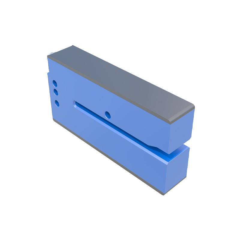
Initial Rough Alignment Procedure
Start with a visual rough alignment. Many through-beam sensors have built-in visual aids. Emitters often have a visible red LED or a "beam spot" indicator that shows where the light is being projected. Receivers may have alignment LEDs that indicate signal strength. Manually point the emitter in the general direction of the receiver. You can use a simple paper target or a piece of white card placed in front of the receiver to see the approximate spot of the emitter's beam. Adjust the emitter's position until the light spot is centered on the receiver's lens. For long-range alignments (over 5 meters), a laser sight or optical alignment tool may be necessary for this initial step.
Fine-Tuning with Indicator LEDs
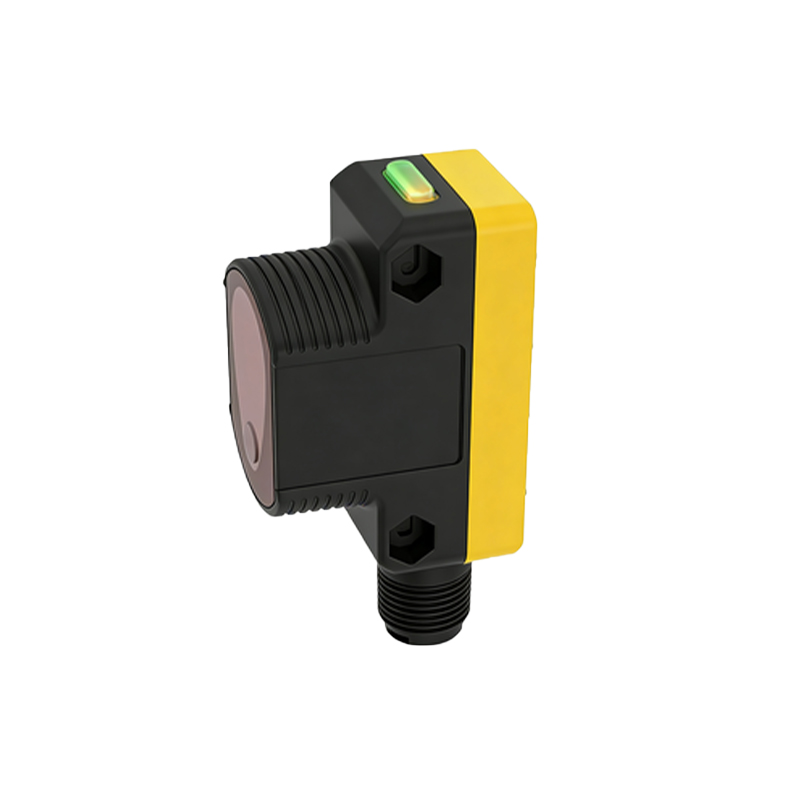
Once power is safely applied to the sensors, use the receiver's alignment indicators for precise tuning. Most receivers feature a series of LEDs—often labeled "STABILITY," "POWER," or simply with bars representing signal strength. A "POWER" or "STABILITY" LED being steadily lit indicates the beam is being received. Some models have a green "beam-on" LED and a red "alignment" or "signal strength" LED that blinks at a rate corresponding to the received light intensity. The goal is to maximize this signal strength. Carefully adjust the emitter (and sometimes the receiver) in minute increments, observing the indicator pattern. Seek the position where the stability LED is brightest and steadiest, or where the alignment LED blinks at its slowest rate, signifying peak signal reception.
Securing Alignment and Testing
After achieving the optimal LED indication, gently tighten the mounting hardware. It is critical to tighten the hardware gradually and alternately (similar to tightening a car wheel) to avoid shifting the alignment during the process. Continuously monitor the receiver's indicator LEDs while tightening to ensure the signal strength does not degrade. Once fully secured, perform a comprehensive test. Pass the target object through the beam at various speeds and positions within the sensing window. The sensor should consistently and reliably detect the object without false triggers. Test under actual operating conditions, if possible, to account for factors like machine vibration, thermal expansion, or airborne particulates that might affect long-term stability.
Troubleshooting Common Alignment Issues
Persistent problems often stem from specific issues. If the signal strength is unstable or weak, check for optical obstructions like dust, oil mist, or condensation on the lenses. Clean lenses with a soft, lint-free cloth. Verify that the emitter and receiver are rated for the operating distance; exceeding the sensor's range will cause failure. Ensure the sensors are not subject to crosstalk from other light sources, including sunlight or other sensor beams. In high-vibration environments, consider using sensors with a "teach" or "learning" function that sets a tolerance window for the signal, or employ rigid, dampened mounting systems. For critical applications, sensors with a visible laser beam or a precise alignment sight can significantly simplify maintenance.
Best Practices for Long-Term Stability
To maintain alignment over the product lifecycle, invest in robust mounting solutions from the start. Use brackets with locking mechanisms that resist loosening due to vibration. Consider installing protective shrouds or guards to prevent physical impact or accumulation of contaminants on the lenses. Implement a periodic maintenance schedule to check alignment and clean optical components. In environments with significant temperature swings, choose sensors and mounting materials with similar coefficients of thermal expansion to minimize drift. Document the alignment settings and indicator LED status during initial commissioning for easier recalibration during future maintenance. Properly aligned through-beam sensors offer the longest sensing ranges and highest reliability, making the initial alignment effort a worthwhile investment for uninterrupted operation.