Understanding Proximity Sensors and Counters
Proximity sensors and counters are fundamental components in modern industrial automation. A proximity sensor is a non-contact device that detects the presence or absence of an object within its sensing range. Common types include inductive, capacitive, and photoelectric sensors. On the other hand, an industrial counter is an electronic instrument that records the number of events or objects passing a specific point. The synergy between these two devices enables precise monitoring and control in processes like production line item counting, machine cycle monitoring, and inventory management. The core principle involves the sensor generating a discrete electrical signal—typically a voltage pulse—upon detecting an object, which is then registered as a single count by the counter.
Key Electrical Interface Considerations
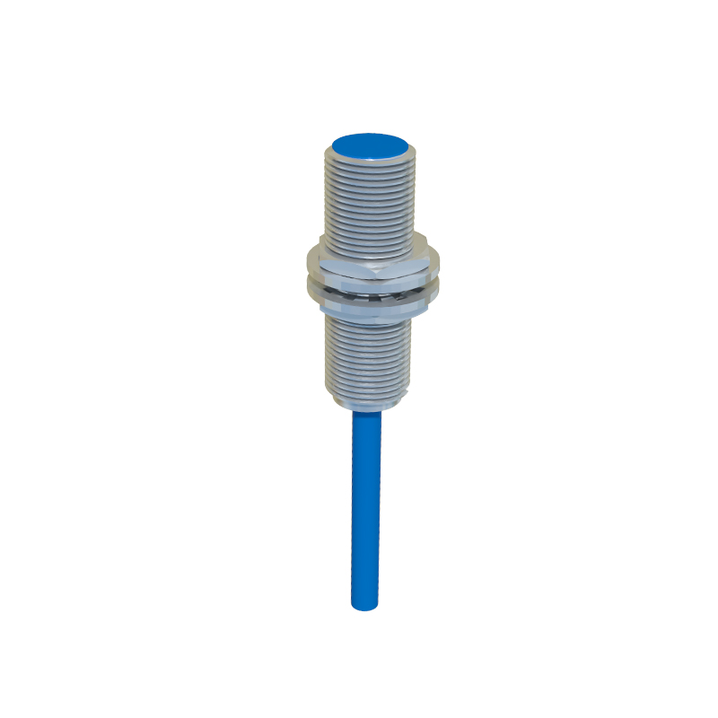
Successful integration hinges on matching the electrical characteristics of the sensor output with the counter input requirements. Most industrial proximity sensors provide either a PNP (sourcing) or NPN (sinking) transistor output. A PNP sensor switches the positive voltage to the load, while an NPN switches the negative or ground side. The counter must be configured to accept the same type of signal. Voltage levels are equally critical; common supply voltages are 12-24 VDC. The sensor's output voltage must be within the counter's input signal range. Additionally, the response time of the sensor must be faster than the minimum pulse width the counter can recognize to ensure no counts are missed during high-speed operations.
Wiring and Connection Diagrams
A standard two-wire DC connection is often insufficient for sensor-counter setups due to leakage current issues. A robust three-wire or four-wire configuration is preferred. For a typical three-wire DC PNP sensor connection: connect the brown wire (positive) to the DC power supply positive, the blue wire (negative) to the supply negative and the counter's common terminal, and the black wire (signal output) directly to the counter's counting input terminal. Always refer to the manufacturer's datasheets for pin assignments. Proper shielding of cables is recommended in electrically noisy environments to prevent false triggering. The power supply for both devices should be stable and adequately rated for the combined load.
Configuring the Counter for Sensor Input
After physical wiring, the counter requires proper configuration. This involves setting parameters such as count mode (up, down, or up/down), preset values for batch control, and the input filter time. The input filter, or debounce setting, is vital. It defines a short time delay during which the input signal must remain stable before being accepted. This prevents contact bounce or electrical noise from causing multiple counts from a single sensor event. For fast-moving objects, set a shorter filter time; for environments with more interference, a slightly longer time may be necessary. Many modern counters also allow selection of the input signal type (e.g., dry contact, NPN, PNP) via software or DIP switches.
Practical Applications and Troubleshooting
A classic application is on a conveyor belt, where an inductive proximity sensor counts metal packages. Each detection pulse increments the counter. When the count reaches a preset value, the counter's relay output can activate a diverter arm or signal a PLC to stop the line. Common issues include missed counts and false counts. Missed counts often stem from insufficient sensor sensing distance, misalignment, or a sensor response time too slow for the object speed. False counts are frequently caused by electrical noise, vibration, or environmental factors like dust affecting optical sensors. Systematic troubleshooting involves checking power, verifying sensor operation with an indicator, measuring output signal with a multimeter, and inspecting the counter's input status LEDs.
Advanced Integration with PLC Systems
While standalone counters are effective, integrating the sensor-counter pair into a Programmable Logic Controller (PLC) system offers greater flexibility. Instead of a dedicated counter module, the proximity sensor can be wired directly to a PLC digital input. The counting logic—including complex functions like resetting, comparing, and generating outputs—is then programmed into the PLC. This centralizes control and allows for easy data logging and integration with Human-Machine Interface (HMI) screens. Whether using a dedicated counter or a PLC, the fundamental principles of sensor selection, interface matching, and noise immunity remain paramount for a reliable and accurate counting system.