Core Sensing Element and Oscillator Circuit
At the heart of an inductive proximity sensor lies its sensing coil, which is wound around a ferrite core. This coil is an integral part of an LC resonant oscillator circuit. When powered, the oscillator generates a high-frequency electromagnetic field that radiates from the active face of the sensor. This field is typically in the range of several hundred kilohertz to a few megahertz. The ferrite core serves to concentrate and direct this electromagnetic field, enhancing the sensor's sensitivity and range. The stability of this oscillator is paramount, as it directly influences the consistency and reliability of the detection signal. The design of the coil, including the number of turns, wire gauge, and core geometry, is meticulously calculated to achieve the desired sensing characteristics for the target application.
Target Interaction and Eddy Current Principle
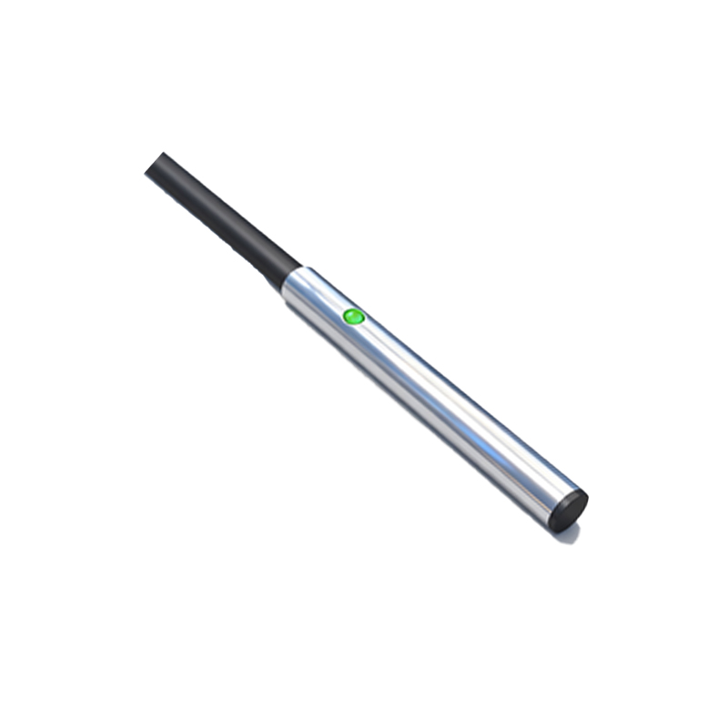
The operational principle is based on electromagnetic induction and the generation of eddy currents. When a conductive metal target enters the oscillating electromagnetic field, eddy currents are induced on the surface of the target. These circulating currents, according to Lenz's law, create their own opposing magnetic field. This opposition results in a load on the sensor's oscillator circuit. The energy loss due to this loading effect is directly proportional to the distance and the conductive properties of the target material. Ferrous metals, due to their magnetic permeability, cause a greater effect, often allowing for a longer nominal sensing distance compared to non-ferrous metals like aluminum or copper.
Signal Evaluation and Demodulation Stage
The change in oscillator amplitude caused by the target's presence is typically very small and requires precise evaluation. The signal from the oscillator is fed into a demodulator or rectifier circuit. This stage converts the attenuated high-frequency AC signal into a corresponding DC voltage level. The amplitude of this DC signal is a direct analog representation of the distance to the target, within the sensor's sensing range. Advanced sensors incorporate temperature compensation circuits at this stage to ensure stable performance across a wide range of operating temperatures, counteracting the inherent drift in electronic components and coil resistance.
Trigger Circuit and Output Switching
The conditioned DC signal is then passed to a trigger circuit, usually a Schmitt trigger with a well-defined hysteresis. This circuit compares the signal level against a preset threshold. When the signal strength exceeds the threshold (indicating a target is within range), the trigger circuit activates the sensor's output switch. The hysteresis prevents rapid on/off toggling when a target is positioned at the very edge of the sensing point, ensuring clean, chatter-free switching. The output stage itself can be a solid-state transistor (PNP or NPN sourcing/sinking) or a mechanical relay in some models, providing the interface to control external devices like PLCs, relays, or indicators.
Housing, Shielding, and Environmental Protection
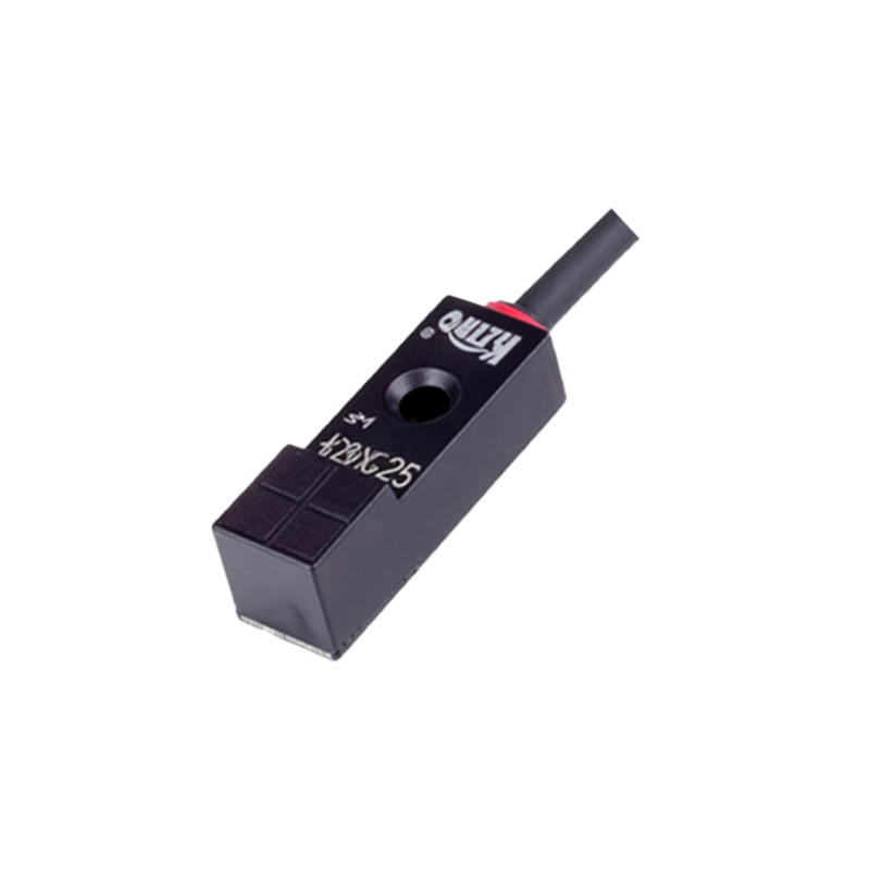
The mechanical structure is critical for robustness. The coil and electronics are potted within a housing, typically made of nickel-plated brass, stainless steel, or high-grade plastics like PBT. Potting with epoxy resin provides exceptional mechanical stability, vibration resistance, and protects against moisture and corrosive agents. A key design feature is the inclusion of a shield or guard around the coil. This shield, often a metal ring, focuses the electromagnetic field axially forward and provides immunity from lateral metal influences, allowing for flush mounting in metal brackets. The housing is rated with an IP (Ingress Protection) code, such as IP67 or IP69K, defining its resistance to dust and water ingress for reliable operation in harsh industrial environments.
Electrical Connections and Configuration
Electrical interfacing is achieved via pre-wired cables or quick-disconnect connectors, such as the standardized M8 or M12 types. The wiring typically includes leads for supply voltage (10-30V DC being most common), ground, and the output signal. Many modern sensors incorporate diagnostic LEDs that indicate power status and output switching. Some advanced models feature IO-Link digital communication, which allows for parameter setting, continuous distance value output, and detailed diagnostic data beyond simple binary switching, enabling predictive maintenance and Industry 4.0 integration.