Introduction to Proximity Sensors
Proximity sensors are indispensable components in modern industrial automation and control systems. These non-contact devices detect the presence or absence of an object within a defined sensing range without any physical contact. Their operation is based on various physical principles, including electromagnetic fields, light, and sound. The primary advantage of proximity sensors lies in their ability to provide reliable, long-term operation in harsh environments where mechanical wear and tear would compromise traditional limit switches. They are widely used in applications such as object counting, position verification, machine safety, and automated assembly lines. Understanding their fundamental working principles is the first step toward effective integration and troubleshooting in any electrical engineering project.
Key Operating Principles and Types
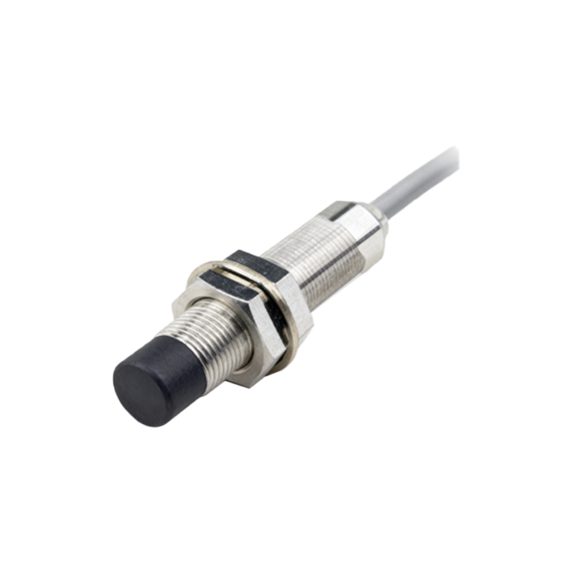
Proximity sensors are broadly categorized based on their detection technology. Inductive proximity sensors are the most common type, generating an electromagnetic field to detect metallic objects. They are highly reliable for detecting ferrous and non-ferrous metals. Capacitive proximity sensors, on the other hand, can detect both metallic and non-metallic materials like plastic, wood, or liquid by sensing changes in capacitance. Ultrasonic sensors use sound waves to detect objects and measure distance, making them suitable for challenging conditions involving transparent or variably colored objects. Finally, photoelectric sensors utilize a light beam, often infrared, to detect the presence of an object. Each type has distinct advantages, selection criteria, and typical applications, which are crucial for engineers to master.
Critical Selection Criteria for Your Application
Selecting the right proximity sensor requires a detailed analysis of the application parameters. Key factors include the sensing distance, which must account for installation tolerances and target material. The target material itself—metal, plastic, liquid—directly dictates whether an inductive, capacitive, or ultrasonic sensor is appropriate. Environmental conditions such as temperature extremes, presence of dust, oil, or chemicals demand sensors with specific ingress protection (IP) ratings. Electrical requirements like operating voltage (e.g., 10-30V DC, 90-250V AC), output type (PNP/NPN, NO/NC), and connection method (2-wire, 3-wire, 4-wire) must align with the control system. Ignoring any of these criteria can lead to sensor failure, inaccurate readings, or system downtime.
Step-by-Step Installation and Wiring Guide
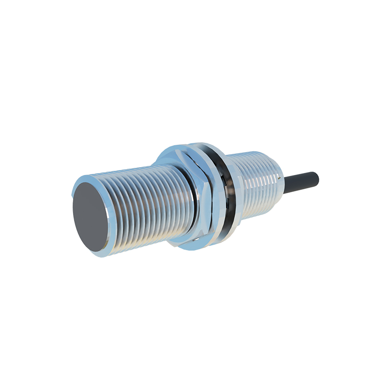
Proper installation is paramount for optimal sensor performance. First, ensure the mounting location is free from interference caused by other electromagnetic sources or adjacent metal structures. For inductive sensors, maintain the recommended lateral and axial spacing between multiple units to prevent mutual interference. Follow the manufacturer's wiring diagram precisely. For a standard 3-wire DC sensor, connect the brown wire to positive voltage (+V), the blue wire to common negative (0V), and the black wire as the switched output to the PLC or controller input. Always implement electrical protection measures such as fuses and surge suppressors. After physical installation, perform a functional test by introducing the target object to verify the sensing distance and output signal stability.
Comprehensive Configuration and Calibration Procedures
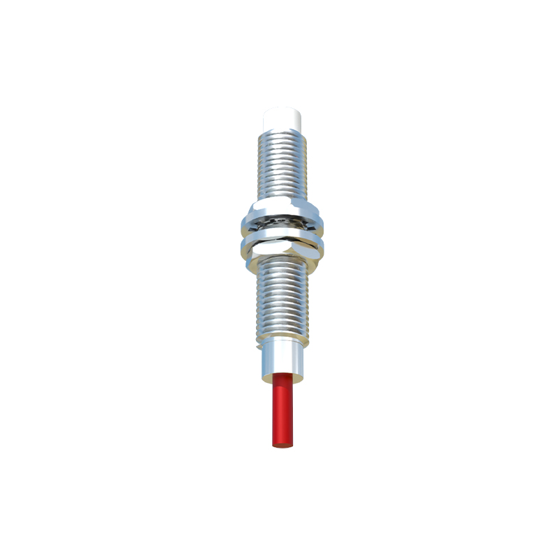
Many advanced proximity sensors feature adjustable parameters for fine-tuning. Sensitivity adjustment allows engineers to set the exact sensing distance, which is critical for ignoring background objects or detecting specific materials. Response time adjustment can optimize the sensor for high-speed applications. Some models include teach-in functions for easy setup. Calibration typically involves using the target object under real operating conditions. For analog output sensors, scaling the 4-20mA or 0-10V output to represent the measured distance or position is a common calibration task. Detailed procedures for these configurations are essential for achieving precise and repeatable detection, which will be thoroughly covered in the accompanying tutorial resources.
Advanced Troubleshooting and Diagnostic Techniques
Even with correct installation, sensors may encounter issues. A systematic troubleshooting approach is vital. Common problems include no output signal, intermittent operation, or shortened sensing range. Begin by checking the power supply voltage with a multimeter at the sensor's terminals. Verify the load connected to the output is within specifications. Inspect for physical damage, accumulated debris on the sensing face, or excessive temperature. Use an oscilloscope to examine the output waveform for noise or instability. Understanding diagnostic LEDs, which indicate power status and output switching, is a quick way to isolate faults. This guide provides a detailed flowchart and case studies to help engineers diagnose and resolve typical sensor failures efficiently.
Download Free Proximity Sensor Tutorial Resources
To empower engineers with practical knowledge, we offer a comprehensive, free-to-download tutorial package. This resource bundle includes a detailed PDF guide expanding on all topics covered here, high-definition wiring diagrams for various sensor types and PLC interfaces, step-by-step configuration checklists