Understanding Hall Effect Sensor Fundamentals
A Hall Effect magnetic proximity sensor operates on the principle of the Hall Effect, where a voltage difference is generated across an electrical conductor when a magnetic field is applied perpendicular to the current flow. This sensor type is widely used for non-contact detection of ferromagnetic objects, position sensing, and speed measurement in industrial automation. Unlike inductive sensors, Hall Effect sensors specifically respond to magnetic fields, making them ideal for applications involving permanent magnets or magnetized targets. The core components include a Hall element, signal conditioning circuitry, and an output stage. Understanding this basic operation is crucial before proceeding to the wiring process, as it informs the necessary connections for power, ground, and output signals to ensure the sensor functions within its specified parameters.
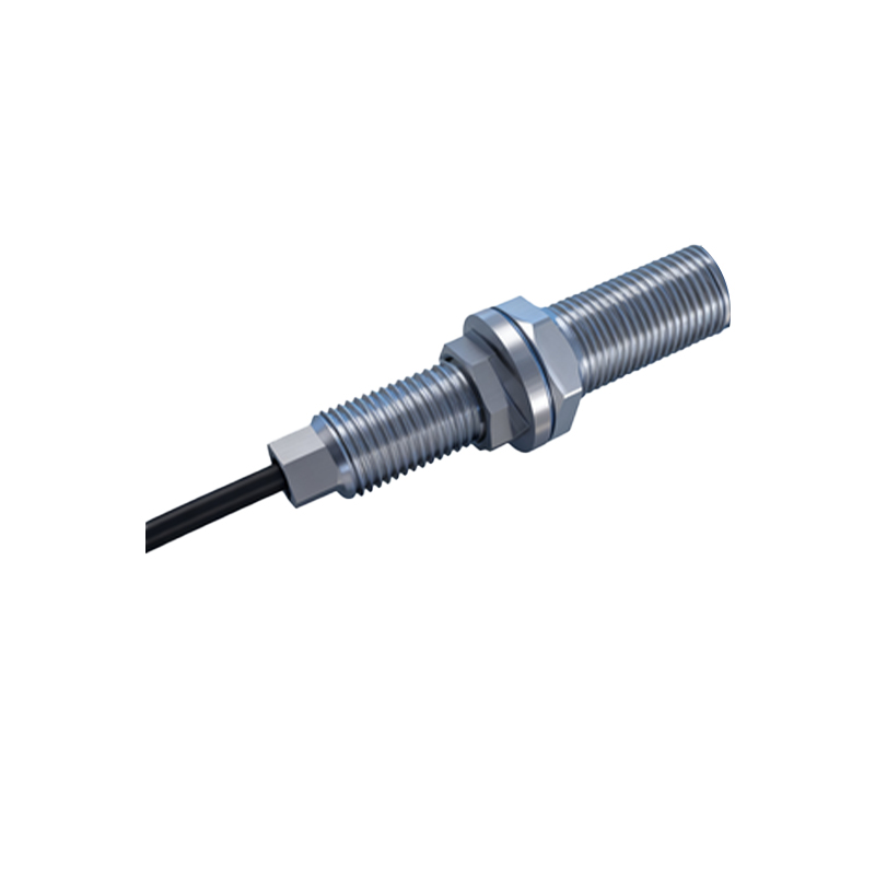
Identifying Sensor Terminals and Specifications
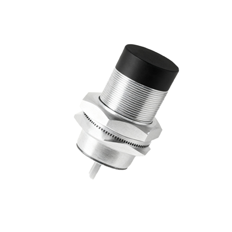
Prior to any wiring, carefully examine the sensor's datasheet and housing. Most industrial Hall Effect proximity sensors have three or four wires, typically color-coded. A common three-wire configuration includes: a brown wire for the positive DC supply voltage (V+), a blue wire for the ground (0V), and a black wire for the output signal. Four-wire sensors often include an additional wire, usually white, for a complementary output or a diagnostic function. It is imperative to verify the voltage range (e.g., 10-30V DC), output type (PNP-sourcing or NPN-sinking), and current rating. The output type dictates how the sensor interfaces with the programmable logic controller (PLC) or load. PNP sensors switch the positive voltage to the load, while NPN sensors switch the ground path. Misidentification can lead to incorrect operation or damage.
Pre-Wiring Safety and Preparation Checklist
Safety is paramount in electrical installations. Ensure all power sources to the control cabinet or machine are locked out and tagged out (LOTO). Gather the necessary tools: appropriate wire strippers, crimping tools, ferrules, screwdrivers, and a digital multimeter. Select the correct wire gauge based on the sensor's current draw and the length of the run to avoid voltage drop. Check the cable specifications for flexibility and shielding, especially in environments with electromagnetic interference (EMI). Plan the cable routing away from high-voltage power lines and motor drives to minimize noise. Have the sensor's mounting bracket and hardware ready, ensuring the sensing face is correctly oriented toward the target magnet with the proper air gap as specified in the manual.
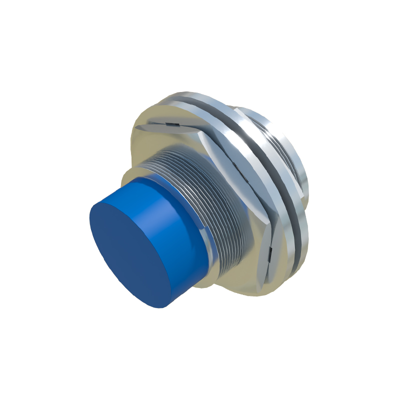
Step-by-Step Wiring Procedure for a Three-Wire DC Sensor
For a standard three-wire DC sensor, follow this procedure. First, prepare the cables. Strip a short length of insulation from the ends of the supply and load wires. It is good practice to use ferrules for a secure connection in terminal blocks. Connect the brown wire (V+) from the sensor to the positive terminal of your DC power supply, typically 24V DC in industrial settings. Connect the blue wire (0V) to the negative terminal or common ground of the same power supply. This provides the operating voltage for the sensor's internal electronics. Next, connect the sensor's output wire (often black). For a PNP sensor, connect this black wire to one terminal of your load (e.g., a PLC input module). The other terminal of the PLC input must then be connected to the power supply's 0V (common). This completes the circuit, allowing the sensor to source current to the PLC when activated.
Connecting to PLCs and Loads: PNP vs. NPN Configurations
The connection to the control system depends entirely on the sensor's output transistor type. For a PNP (sourcing) sensor, the output acts as a switch for the positive voltage. As described, the black output wire goes to the PLC input. The PLC input's common point is connected to 0V. When a magnet is detected, the PNP transistor turns on, connecting the PLC input to V+, thus signaling a HIGH or "ON" state. For an NPN (sinking) sensor, the output switches the ground path. Here, the black output wire is connected to the PLC input, but the PLC input's common point must be connected to V+ (24V). When activated, the NPN transistor connects the PLC input to 0V, creating a current sink and signaling a LOW or "ON" state. Always confirm your PLC input module is compatible with the sinking or sourcing signal.
Testing, Troubleshooting, and Commissioning
After wiring, do not immediately power the entire system. First, perform a continuity check with a multimeter (power