Introduction to Photoelectric Sensing Technology
Photoelectric sensors are fundamental components in modern industrial automation, serving as the critical link between the physical world and control systems. These devices operate by emitting a beam of light, typically from an LED or laser diode, and detecting changes in the received light signal caused by the presence, absence, or characteristics of a target object. The core principle hinges on the photoelectric effect, where light energy is converted into an electrical signal. This conversion is not a simple on/off switch; it is governed by a precise and definable relationship between the input (the optical signal interacting with the target) and the output (the electrical signal sent to the controller). This relationship is the sensor's transfer function, a concept central to understanding its performance, limitations, and optimal application in complex systems.
Defining the Transfer Function
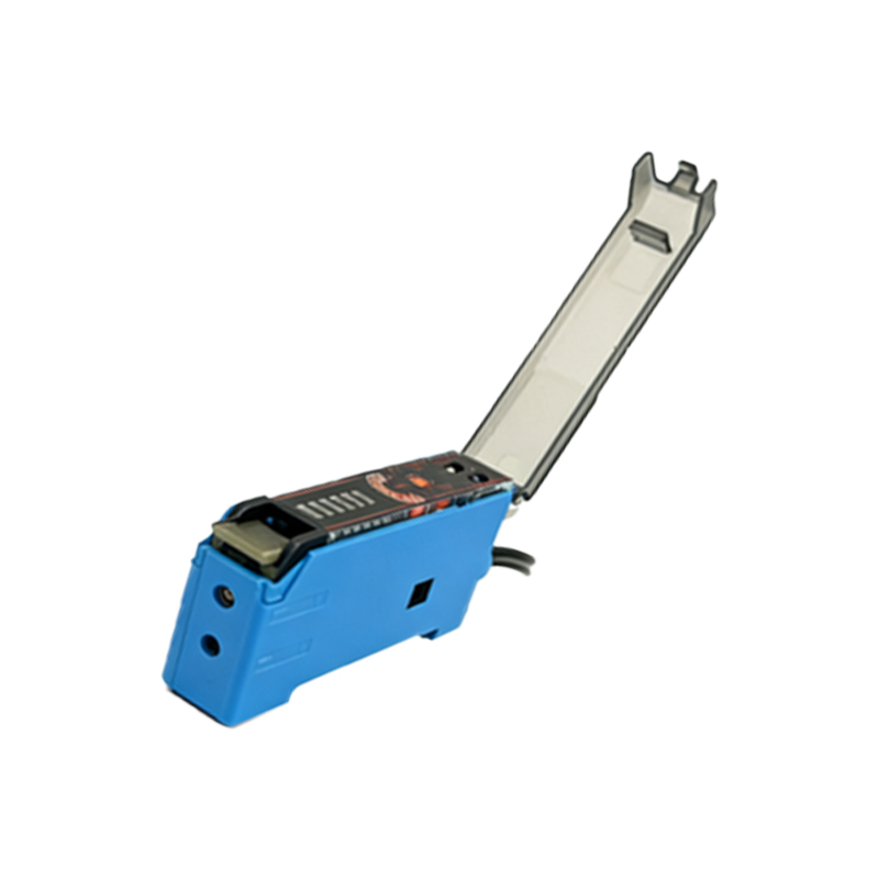
In engineering terms, a transfer function is a mathematical representation of the relationship between the output and input of a system. For a photoelectric sensor, the input is the modulated light signal received by the photodetector (phototransistor or photodiode), and the output is the resulting electrical signal, usually a switched DC voltage or a current. The transfer function describes how the sensor responds to variations in light intensity, target reflectivity, distance, and environmental conditions. It defines parameters such as sensitivity, hysteresis, linearity (for analog sensors), and response time. Essentially, it quantifies the "transfer" of information from the optical domain to the electrical domain, detailing how faithfully and quickly the electrical output represents the physical event being sensed.
Key Components Influencing the Transfer Curve
Several internal and external factors shape the sensor's transfer characteristics. Internally, the wavelength of the emitted light, the lens design for beam focusing, the type and sensitivity of the photodetector, and the signal processing circuitry are paramount. For instance, a sensor with a focused laser beam will have a steeper, more defined transfer curve at its sensing point compared to a diffuse sensor with a broader detection field. Externally, the target's surface properties (color, material, finish), its distance from the sensor (operating within the specified sensing range), and ambient light conditions all act as inputs that shift or scale the transfer function. Contamination on the lens or target can attenuate the light signal, effectively altering the input and leading to a faulty output if not accounted for.
Types of Transfer Functions: Digital vs. Analog
Photoelectric sensors primarily fall into two categories based on their output and, consequently, their transfer function. Digital (or switching) sensors have a binary transfer function. The output switches states (e.g., from 0V to 24V) when the received light intensity crosses a predefined threshold. This function features hysteresis—a difference between the turn-on and turn-off points—to prevent output chatter when the signal is near the threshold. Analog sensors provide a continuous output (e.g., 4-20 mA or 0-10V) proportional to the received light intensity or distance. Their transfer function is often linear within a specific range, allowing them to measure parameters like transparency, thickness, or precise position. Understanding which type of transfer function is required is crucial for selecting the right sensor for the application, be it object detection, counting, or precise measurement.
The Role of Signal Processing and Conditioning
Modern photoelectric sensors incorporate sophisticated electronics to shape and stabilize the transfer function. The raw signal from the photodetector is weak and noisy. Amplifiers boost this signal, while filters (synchronous demodulation is common) are used to reject ambient light noise, such as from factory lighting or sunlight. Microcontrollers implement algorithms for background suppression, temperature compensation, and teach-in functionality (where the sensor learns the specific conditions for switching). This internal conditioning ensures that the final, usable output presented to the PLC or machine controller has a clean, reliable, and repeatable relationship to the physical event, regardless of minor environmental fluctuations. It makes the transfer function robust and dependable in harsh industrial settings.
Practical Implications for System Design and Troubleshooting
A deep understanding of the photoelectric sensor's transfer function is invaluable for system design and maintenance. When designing an application, engineers must consider the operating point on the transfer curve. They must ensure sufficient signal margin—the difference between the received signal from the target and the sensor's switching threshold—to account for wear, contamination, or misalignment over time. During troubleshooting, an oscilloscope can be used to monitor the sensor's analog signal (if available) to see the actual input to the transfer function. A declining signal margin indicates a problem like a dirty lens, misaligned sensor, or deteriorating light source. By interpreting the sensor's behavior through the lens of its transfer function, engineers can diagnose issues proactively, optimize system performance, and ensure long-term reliability in automated production lines, packaging machinery, and material handling systems.