Introduction to Dual-Light Photoelectric Sensors
Dual-light photoelectric sensors, also known as through-beam sensors with separate emitter and receiver units, are fundamental components in industrial automation for precise object detection. Unlike diffuse or retro-reflective types, these sensors consist of two independent housings: one emitting a focused light beam (typically infrared, red, or laser) and the other receiving it. Detection occurs when an object interrupts the light path between the emitter and receiver. This design offers superior sensing ranges, high immunity to environmental interference, and reliable operation even with objects of varying colors or surface finishes. Understanding their wiring is critical for ensuring optimal performance, safety, and integration into control systems such as PLCs (Programmable Logic Controllers).
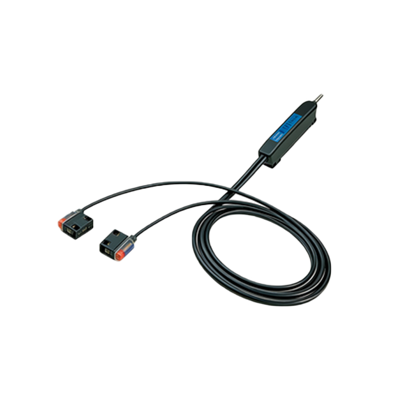
Key Components and Terminal Identification
Before examining the wiring diagram, it is essential to identify the standard terminals on both the emitter and receiver units. The emitter unit is relatively simple, usually featuring two terminals: a brown wire (or terminal labeled +V, L+, or 24VDC) for the positive power supply and a blue wire (or terminal labeled 0V, L-, or COM) for the common negative. Its sole function is to project a continuous or modulated light beam. The receiver unit is more complex. Common terminals include: brown (+V) and blue (0V) for power; a black wire (or terminal labeled OUT, NO, or Signal) which is the switching output; and sometimes a white wire (for output configuration or complementary output). Many receivers also have a yellow or green wire for diagnostic LED control or teach-in functions. Always consult the specific datasheet, as colors and functions can vary by manufacturer (e.g., Omron, Sick, Keyence).
Standard Wiring Diagram for NPN Output Configuration
The most common wiring configuration in many regions is the NPN (sinking) output. In this setup, the load (e.g., a PLC input, relay coil, or indicator lamp) is connected between the receiver's output terminal (black wire) and the positive supply voltage (+V). Here is a step-by-step breakdown: First, connect the DC power supply. Link the positive terminal (+24VDC) to the brown wires of both the emitter and receiver. Connect the supply's negative terminal (0VDC) to the blue wires of both units. This provides operational power. For the receiver's output, connect the black wire (NPN output) to one side of your load device. Connect the other side of the load directly to the positive supply rail (+24VDC). When no object blocks the beam, the receiver's internal switch is open, and no current flows to the load. When an object interrupts the beam, the NPN transistor switches ON, closing the circuit between the black wire and the blue wire (internal 0V), allowing current to flow from +V, through the load, into the black wire, and out through the blue wire to complete the circuit, thus activating the load.
Standard Wiring Diagram for PNP Output Configuration
In PNP (sourcing) output configurations, common in Europe, the load is connected between the receiver's output and the common negative (0V). The power connections remain identical: brown wires to +24VDC and blue wires to 0VDC. The key difference lies in the output circuit. Connect one side of the load device directly to the 0VDC (common negative) rail. Connect the other side of the load to the receiver's black wire (now a PNP output). In the normal, unbroken beam state, the internal PNP transistor is off. When the beam is blocked, the transistor switches ON, sourcing current from the internal +V. This creates a circuit where current flows from the receiver's internal +V, out through the black wire, through the load, and back to the 0VDC supply. This configuration actively provides a positive voltage signal to the load upon detection.
Wiring Considerations for Shielded Cables and Noise Immunity
For long-distance installations or electrically noisy environments (near motors, VFDs, or welding equipment), proper cabling is paramount. Always use shielded, twisted-pair cables for both the emitter and receiver. Connect the cable shield drain wire to the functional earth (FE) or ground terminal (usually a green/yellow wire or a dedicated metal clamp on the sensor housing) at the receiver end only. Do not connect the shield at both ends to avoid ground loops. Ensure this ground point is connected to a clean, low-impedance earth ground. Keep high-voltage power lines and sensor cables separated by at least several inches. For very long runs exceeding the sensor's rated distance, consider using relay amplifiers or choosing models designed for extended range. Additionally, some sensors offer complementary outputs (NO and NC) or teach-in modes via specific wiring sequences to the auxiliary (white) wire, which require precise adherence to the manual.
Integration with PLC and Diagnostic Circuitry
Integrating the sensor with a PLC involves connecting the output signal to a PLC digital input module. For an NPN sensor, the PLC input card must be configured for PNP/sourcing input (as the current *sources* from the PLC card into the sensor's sinking output). For a PNP sensor, the PLC input should be configured for NPN/sinking. Always verify voltage compatibility (typically 24VDC). To implement a basic diagnostic circuit for monitoring sensor health or beam status, wire the receiver's yellow (or similar) diagnostic output to a separate PLC input or an indicator lamp. This output often activates when the sensor is powered and functional but the beam is blocked, providing a separate signal from the main detection output. This aids in troubleshooting without interrupting the main control logic.
Safety Precautions and Final Testing
Prior to energizing the circuit, double-check all connections against the manufacturer's diagram. Ensure the power supply voltage matches the sensor rating (commonly 10-30VDC). Use properly sized fuses or circuit breakers in the power line for protection. Verify that the emitter and receiver are securely mounted in perfect optical alignment; most units have alignment LEDs that turn steady when correctly aimed. After powering on, perform a functional test by passing an object through the beam. Confirm the output switches states and the connected load (e.g., pilot light, relay) responds appropriately. Check for stable operation without false triggering. Proper wiring not only guarantees reliability but also extends the operational lifespan of the sensors in demanding industrial applications.