Introduction to Inductive Proximity Sensors
Inductive proximity sensors are non-contact electronic devices used for detecting metallic objects within their sensing range. Operating on the principle of electromagnetic induction, these sensors generate an oscillating electromagnetic field from a coil wound around a ferrite core. When a metallic target enters this field, eddy currents are induced in the target, causing a change in the oscillation amplitude or frequency. This alteration is detected by the sensor's internal circuitry, which triggers an output signal. Widely employed in industrial automation, these sensors offer high reliability, durability, and resistance to environmental factors like dust, moisture, and vibration. Their ability to function without physical contact minimizes wear and tear, making them ideal for harsh manufacturing environments.
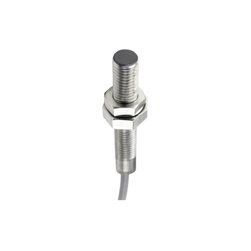
Core Design Components
The design of an inductive proximity sensor revolves around several key components. The coil, typically made of copper wire, is wound around a ferrite core to concentrate the magnetic field. An oscillator circuit generates a high-frequency electromagnetic field, while a demodulator converts changes in oscillation into electrical signals. The output stage, which may include transistors or relays, provides the switching signal. Shielding is critical to prevent external interference and ensure directional sensitivity. Designers must carefully select materials for the housing, often using stainless steel or plastic, to protect internal electronics from mechanical stress and chemical exposure. Additionally, factors like sensing distance, target material, and operating temperature influence component choices, requiring precise calculations to optimize performance.
Operating Principles and Sensing Range
Inductive proximity sensors operate based on Faraday's law of electromagnetic induction. The oscillator produces a fluctuating magnetic field that extends from the sensor face. When a conductive metal object approaches, eddy currents form on its surface, absorbing energy from the field and reducing oscillation amplitude. This drop is detected by a threshold circuit, activating the output. The sensing range depends on factors such as coil size, oscillator frequency, and target material. Ferrous metals like iron typically yield longer ranges due to higher permeability, while non-ferrous metals like aluminum require adjustments in design. Standard sensing distances range from a few millimeters to several centimeters, with shielded designs offering shorter, more focused ranges compared to unshielded versions. Engineers must account for temperature variations and supply voltage stability to maintain consistent detection.
Circuit Design and Signal Processing
The electronic circuitry of an inductive proximity sensor is designed for stability and sensitivity. A typical circuit includes an LC oscillator, where the coil acts as the inductor, resonating at a specific frequency. As a target approaches, the inductance changes, causing a frequency shift or amplitude modulation. A demodulator extracts this signal, which is then amplified and compared to a reference voltage in a comparator circuit. If the signal exceeds the threshold, the output switches states. Advanced sensors incorporate microcontrollers for digital signal processing, enabling features like programmable sensing distances and diagnostics. Power supply considerations, such as DC or AC voltage compatibility, and protection against reverse polarity or short circuits, are integral to circuit design to ensure longevity in industrial settings.
Environmental Considerations and Durability
Industrial environments pose challenges like extreme temperatures, humidity, and mechanical shocks, which impact sensor performance. Designers address these by selecting robust materials and implementing protective measures. Housing materials like nickel-plated brass or PBT plastic provide corrosion resistance, while epoxy resin seals protect internal components from moisture and dust, often meeting IP67 or IP69K ratings. Temperature compensation circuits maintain accuracy across operating ranges, typically from -25°C to 70°C. Additionally, sensors are tested for electromagnetic compatibility (EMC) to prevent interference from nearby motors or power lines. Vibration resistance is achieved through solid-state designs without moving parts, ensuring reliable operation in applications like conveyor systems or robotic arms.
Applications in Industrial Automation
Inductive proximity sensors are ubiquitous in automation due to their precision and resilience. Common applications include position detection in machinery, such as verifying the presence of metal parts on assembly lines. They serve as limit switches in robotic systems, ensuring safe movement by detecting end positions. In packaging industries, sensors count metallic items or monitor fill levels. Automotive manufacturing relies on them for weld seam tracking and component alignment. Their non-contact nature makes them suitable for high-speed operations, reducing downtime and maintenance. Integration with PLCs (Programmable Logic Controllers) allows for seamless control in complex processes, enhancing efficiency and safety in sectors like food processing, pharmaceuticals, and material handling.
Future Trends and Innovations
Advancements in inductive proximity sensor technology focus on miniaturization, smart features, and enhanced connectivity. Smaller sensors with integrated ASICs (Application-Specific Integrated Circuits) enable compact designs for space-constrained applications. IoT (Internet of Things)