Understanding Proximity Sensor Fundamentals
Proximity sensors, often referred to as "inductive sensors" or "proximity switches," are non-contact devices that detect the presence or absence of metallic objects within their sensing range. These sensors operate on the principle of electromagnetic induction. When a metal target enters the sensor's electromagnetic field, it causes a change in the oscillation amplitude within the sensor's internal coil. This change is detected by the sensor's circuitry, which then triggers a solid-state output signal. The key advantages of these sensors include high reliability, long operational life, and immunity to environmental factors like dust, oil, and moisture, making them ideal for harsh industrial environments. Their non-contact nature eliminates mechanical wear and tear, ensuring consistent performance over millions of cycles. Common types include shielded (flush-mountable) and unshielded (non-flush) designs, each suited for specific mounting and sensing applications.
Selecting the Right Sensor for Your Application
Choosing the correct proximity sensor is critical for system performance. Key selection parameters include sensing distance, target material, size, and the required output type. Standard sensing distances typically range from 1 to 40 millimeters, depending on the sensor size and model. It is essential to note that the rated sensing distance is specified for a standard mild steel target. For other metals like aluminum or copper, a correction factor must be applied, as these materials reduce the effective sensing range. Output configurations are another vital consideration. Sensors are available with NPN (sinking) or PNP (sourcing) transistor outputs, as well as analog (4-20 mA or 0-10V) or IO-Link digital communication outputs. The choice depends on the control system's input card compatibility. Environmental ratings, such as IP67 or IP69K for water and dust resistance, and operating temperature ranges must also align with the installation conditions.
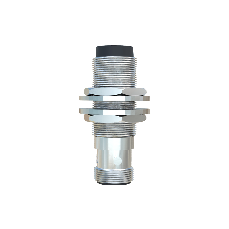
Wiring and Electrical Connection Procedures
Proper wiring is fundamental to safe and reliable sensor operation. Most industrial proximity sensors have a three-wire or four-wire configuration. For a standard DC three-wire sensor, the wires are typically brown (positive supply), blue (negative supply or common), and black (output signal). The first step is to disconnect all power sources to the control cabinet. Connect the brown wire to the positive DC voltage terminal (e.g., +24V DC) and the blue wire to the 0V DC common terminal. The black output wire is then connected to the input channel of the PLC or controller. For PNP sensors, the output provides positive voltage to the load; for NPN sensors, it sinks current to ground. Always refer to the manufacturer's datasheet for the exact pinout and wiring diagram. Ensure wire gauges are appropriate for the current load, and use conduit or cable carriers to protect wires from physical damage and electrical interference.
Mounting and Mechanical Installation Best Practices
Correct mechanical installation ensures accurate and repeatable detection. For flush-mounted (shielded) sensors, they can be installed flush with a metal bracket without affecting the sensing field. Non-flush (unshielded) sensors require a clear space around the sensing face to achieve their full rated range; mounting them flush will reduce the sensing distance. The sensor should be positioned so that the target approaches the sensing face perpendicularly for optimal performance. Avoid mounting sensors directly facing each other, as mutual interference can cause false triggering. Maintain a minimum distance between two adjacent sensors, usually three times the sensor diameter, to prevent crosstalk. Use high-quality mounting brackets and tighten fasteners to the specified torque to prevent vibration-induced loosening. Regularly check for mechanical misalignment caused by machine vibration or thermal expansion.
Configuration, Testing, and Commissioning
After installation, sensors must be configured and tested. For basic digital sensors, this involves verifying the output state with and without a target present using a multimeter or the PLC's input status indicators. Many modern sensors feature LED indicators that show power status and output activation. For sensors with adjustable parameters, such as sensing distance hysteresis or output delay, use the provided teach-in button or an IO-Link master to set the parameters according to the application needs. During commissioning, perform a full operational test by cycling the target through its normal path at the required speed. Monitor for any missed detections or false signals. Document the sensor's part number, installation location, and any custom settings for future maintenance reference.
Troubleshooting Common Connection Issues
Even with proper installation, issues can arise. A sensor not detecting a target could be due to an incorrect power supply voltage, wiring fault, or the target being outside the effective sensing range. First, verify the supply