Introduction to Proximity Sensors in CNC Tool Magazines
In the realm of Computer Numerical Control (CNC) machining, the tool magazine stands as a critical component for automated tool changing, directly impacting machine uptime and productivity. Proximity sensors serve as the unsung heroes within these systems, providing the essential non-contact detection required for precise tool positioning, presence verification, and overall magazine management. These sensors operate by generating an electromagnetic field and detecting changes caused by a metallic target—typically the tool holder or a designated flag on the magazine carousel. Their ability to function without physical contact eliminates mechanical wear, ensures long-term reliability, and maintains consistent accuracy, which is paramount in high-speed, high-precision manufacturing environments. The selection and integration of the correct proximity sensor are fundamental to achieving seamless, unattended machining operations.
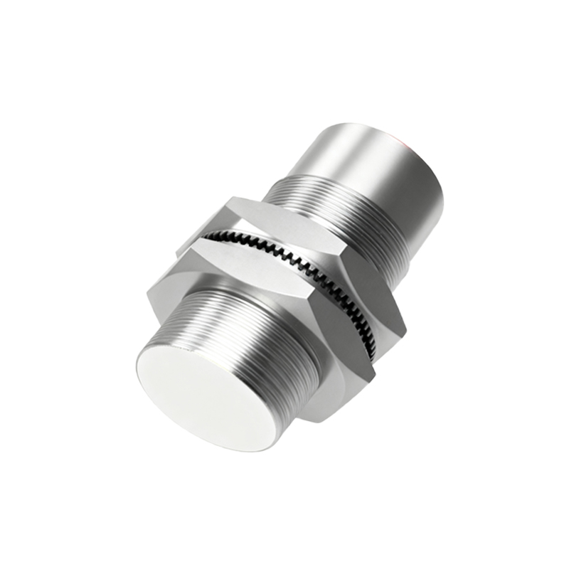
Key Operational Principles and Sensor Types
The primary technology employed in CNC tool magazines is the inductive proximity sensor. This sensor type is ideal for detecting metallic objects, such as the steel or carbide tool holders. It consists of an oscillator circuit that creates a high-frequency electromagnetic field emanating from the sensor's face. When a conductive metal target enters this field, eddy currents are induced on the target's surface. This action dampens the oscillator's amplitude, a change which is detected by the sensor's circuitry, triggering a solid-state output signal. For applications requiring detection of non-metallic objects or specific conditions, capacitive or magnetic sensors might be utilized, though inductive types dominate tool magazine applications due to their robustness, speed, and immunity to environmental contaminants like coolant mist and metal chips.
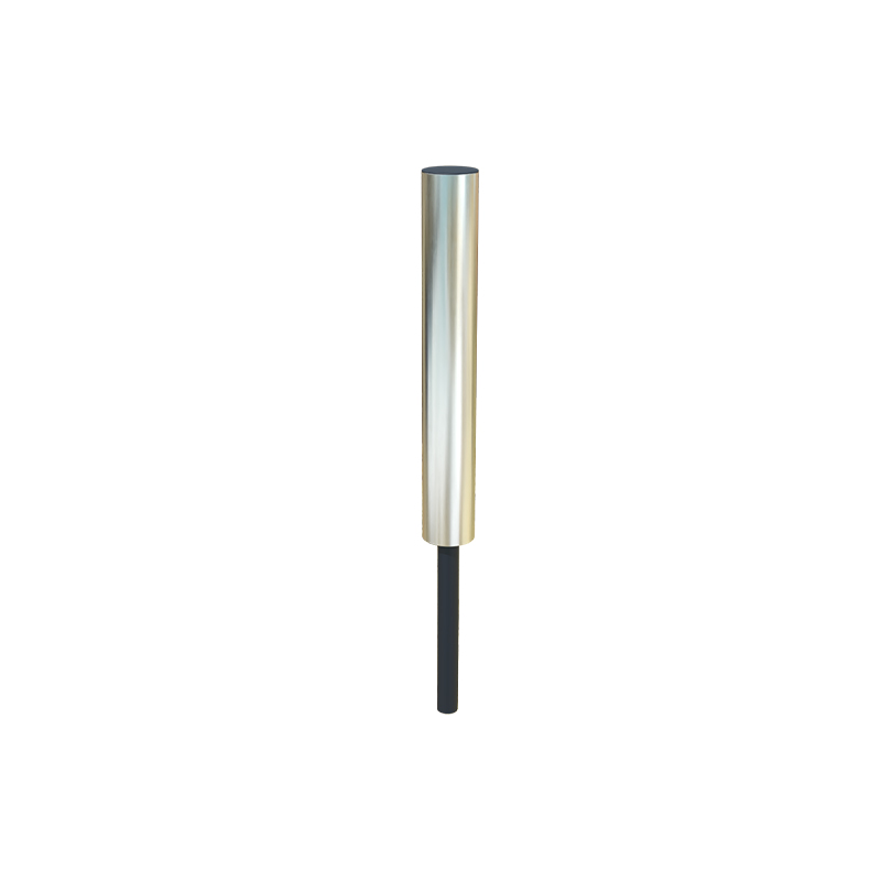
Critical Applications for Tool Positioning and Verification
Within a CNC tool magazine, proximity sensors fulfill several non-negotiable functions. The most crucial is tool presence verification. Before a tool change command is executed, a sensor must confirm that the expected tool is physically present in its designated pocket or station. This prevents catastrophic collisions where the spindle might attempt to pick up a non-existent tool. Secondly, sensors are used for magazine position indexing. They detect reference points or flags on the rotating carousel or chain-type magazine, providing feedback to the CNC controller to ensure it stops precisely at the correct tool station. Furthermore, sensors monitor the status of tool clamping mechanisms, verifying whether a tool is securely locked in the magazine or properly released for exchange.
Selection Criteria for Optimal Performance
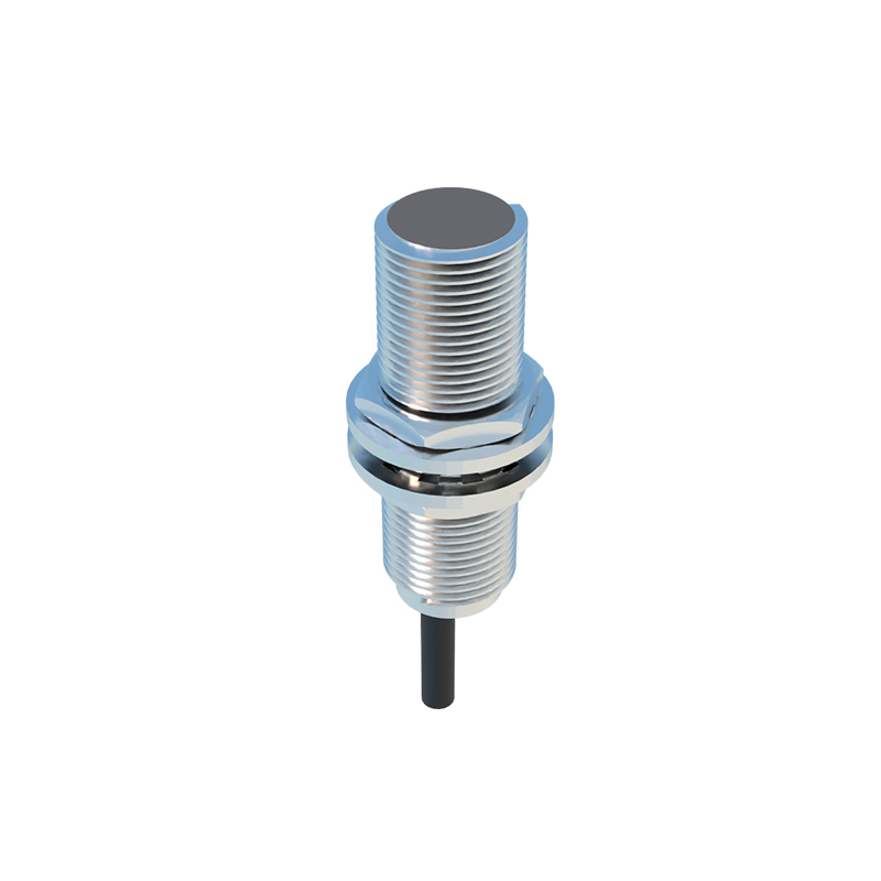
Choosing the right proximity sensor demands careful consideration of several technical parameters. Sensing range, or the nominal distance at which the sensor can reliably detect its target, must be matched to the mechanical clearances within the compact magazine assembly. The sensor's housing material and ingress protection (IP) rating are critical; they must withstand constant exposure to coolants, lubricants, and metallic particulate, typically requiring ratings of IP67 or higher. Electrical characteristics, such as the output type (PNP/NPN) and voltage rating, must be compatible with the machine's control system. Additionally, factors like switching frequency (response speed) and temperature stability ensure the sensor can keep pace with rapid tool change cycles and operate reliably in the variable thermal conditions of a machine shop.
Installation, Alignment, and Maintenance Best Practices
Proper installation is paramount for reliable sensor operation. The sensor must be securely mounted to prevent vibration-induced misalignment, which can lead to intermittent faults or failure to detect. The alignment between the sensor's sensing face and the target is critical; even a slight angular misalignment can significantly reduce the effective sensing range. Maintenance primarily involves regular cleaning of the sensor face to remove any buildup of oil, grease, or metal dust that could insulate the sensing field. Diagnostic LEDs, present on most modern sensors, provide immediate visual feedback on power status and output switching, aiding in rapid troubleshooting. A proactive maintenance schedule that includes periodic functional checks can prevent unplanned downtime.
Addressing Common Challenges and Troubleshooting
Despite their robustness, proximity sensors can encounter issues. False triggering is a common problem, often caused by the detection of unintended metallic objects, such as adjacent tool holders or the magazine structure itself. This is resolved by careful sensor placement, shielding, or selecting a sensor with a reduced or more focused sensing range. Signal drift or complete failure can result from physical damage, severe contamination, or electrical overloads. Troubleshooting typically involves verifying power supply, checking for proper target alignment and condition, inspecting for physical damage to the sensor or cable, and using a multimeter to test the output signal. Understanding the machine's ladder logic or diagnostic pages can help pinpoint whether a fault is sensor-related or lies elsewhere in the control sequence.
The Future: Integration with Industry 4.0 and Smart Manufacturing
The evolution of proximity sensors is closely tied to the advancement of smart