Introduction to Proximity Sensing in Pump Systems
Proximity switch sensors are indispensable components in modern industrial pump systems, particularly for monitoring the position, speed, and operational status of pump gears. These non-contact sensors detect the presence or absence of a metallic target—such as a gear tooth—without physical interaction, thereby eliminating mechanical wear and ensuring long-term reliability. In critical applications like centrifugal pumps, positive displacement pumps, and gear pumps, precise timing and synchronization are paramount. A proximity sensor, often an inductive type, is strategically mounted near the gear to generate a pulse signal each time a gear tooth passes by. This pulse train provides real-time data on rotational speed, direction, and can trigger alarms for conditions like cavitation, jamming, or unexpected stoppage. The robustness of these sensors against harsh environments—including exposure to lubricants, high temperatures, and vibration—makes them the preferred choice for engineers designing maintenance-friendly and efficient pumping solutions.
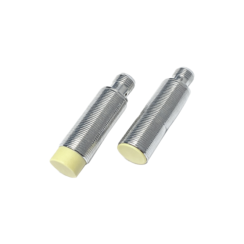
Core Operating Principles and Sensor Types
The most common technology employed for pump gear monitoring is the inductive proximity sensor. It operates by generating an oscillating electromagnetic field from its active face. When a ferrous or non-ferrous metallic gear tooth enters this field, it induces eddy currents within the target, causing a change in the oscillation amplitude. This change is detected by the sensor's internal circuitry, which subsequently switches its output state. For applications involving non-metallic gears or where greater sensing distances are required, capacitive proximity sensors may be utilized. They detect changes in capacitance caused by any material entering their field. Hall-effect sensors are another variant, specifically used for detecting the magnetic fields from magnets embedded in or mounted on the gear assembly. The selection depends on factors like target material, required sensing distance, switching frequency (critical for high-speed gears), and environmental conditions such as temperature and potential chemical exposure.
Critical Installation and Alignment Considerations
Proper installation is crucial for optimal sensor performance and accurate gear monitoring. The sensor must be mounted securely to withstand the inherent vibrations of a running pump. The alignment between the sensor's sensing face and the gear tooth is critical; even minor misalignment can lead to missed pulses or false triggers. Engineers must carefully calculate the mounting distance (usually a fraction of the sensor's nominal sensing range) to ensure the gear tooth reliably enters the active field without risk of physical collision. The air gap between the sensor and the tip of the gear tooth must be consistently maintained. For detecting individual teeth, the sensor face is often aligned axially to the gear. For speed measurement via a single protruding target on the gear side, radial alignment is common. Environmental sealing, typically rated IP67 or higher, is mandatory to protect the sensor from ingress of oil, coolant, or washdown fluids commonly present in pump systems.
Integration with Control and Monitoring Systems
The output from a proximity sensor is a digital signal, typically in the form of a PNP or NPN transistor switch, or a Namur output for hazardous areas. This signal is fed directly into a Programmable Logic Controller (PLC), a frequency converter, or a dedicated monitoring module. Within the PLC, ladder logic or function block programming is used to count pulses over time to calculate RPM, monitor for under-speed or over-speed conditions, and determine total operational runtime for predictive maintenance schedules. Advanced systems can perform spectral analysis on the pulse signal to detect anomalies indicative of gear wear, tooth damage, or shaft misalignment before catastrophic failure occurs. The integration allows for automated system responses, such as shutting down the pump, activating a standby unit, or alerting maintenance personnel via SCADA systems, thereby enhancing overall system safety and uptime.
Advantages Over Traditional Mechanical Switches
The transition from mechanical limit switches or cam-operated switches to electronic proximity sensors represents a significant technological advancement. Proximity sensors offer superior longevity due to the absence of moving parts that are subject to wear and fatigue. They provide much faster response times, enabling accurate monitoring of high-speed pump gears without signal bounce. Their solid-state construction ensures consistent operation despite contamination from grease or grime, whereas mechanical contacts can fail due to pitting or fouling. Furthermore, proximity sensors are not affected by inertia, allowing for precise detection regardless of acceleration or deceleration phases of the pump motor. This reliability translates directly into reduced maintenance costs, minimized unplanned downtime, and more granular data collection for optimizing pump efficiency and lifecycle management.
Selection Criteria and Best Practices
Selecting the right proximity sensor for a pump gear application requires a systematic evaluation of several parameters. First, define the target material and shape (gear tooth profile). Next, determine the required sensing distance, ensuring a safety margin to account for thermal expansion and mechanical tolerances. The sensor's housing material (