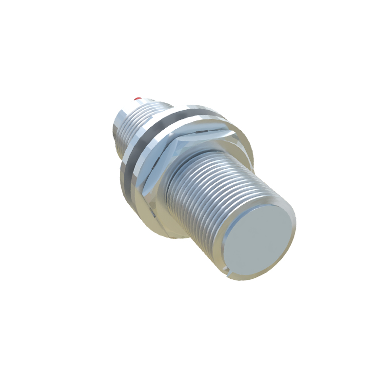
In the world of industrial automation and machinery control, precision and reliability are non-negotiable. Among the myriad of components that ensure seamless operation, gear sensor proximity switches stand out as critical, yet often understated, devices. These sensors are the silent sentinels, monitoring rotational speed, detecting position, and safeguarding complex mechanical systems from catastrophic failure. Unlike optical or manual methods, they offer robust, contactless sensing in the harshest of environments.
At its core, a gear sensor proximity switch is an inductive proximity sensor specifically designed to detect the teeth of a rotating gear. It does not make physical contact with the target. Instead, it generates an electromagnetic field. When a gear tooth enters this field, it causes a detectable change—typically in inductance or eddy currents—which the sensor's internal oscillator and trigger circuit convert into a clear, digital output signal. Each passing tooth generates a pulse. By counting these pulses over time, the system can calculate precise rotational speed (RPM). Furthermore, by monitoring the sequence or absence of pulses, it can determine position, direction of rotation, and even detect missing teeth or misalignment.
The typical construction involves a robust housing, often made of stainless steel or nickel-plated brass, to withstand vibration, oil, coolant, and metal chips. The sensing face is precisely engineered to provide an optimal field for tooth detection. Key performance specifications include sensing distance, which is relatively short (often 1-3 mm) for high accuracy, operating frequency (the maximum number of pulses per second it can handle), and output type (PNP/NPN, analog, or a dedicated speed switch). The output is a clean, square-wave signal ideal for direct interface with PLCs (Programmable Logic Controllers), counters, tachometers, or control systems.
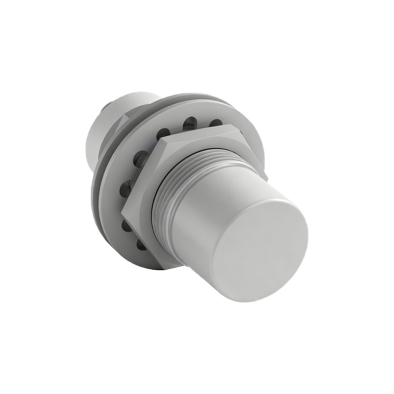
The advantages of using gear sensor proximity switches are compelling. Their contactless nature means no wear and tear, leading to exceptionally long service life and minimal maintenance. They are immune to dirt, dust, oil, and moisture that would foul optical encoders. They provide high-resolution feedback because each tooth generates a pulse, allowing for very precise speed measurement. Their solid-state design ensures fast response times, critical for high-speed applications or instant fault detection. Finally, their installation is straightforward, requiring only proper alignment and gap setting.
These sensors are indispensable across a vast spectrum of industries. In automotive manufacturing, they monitor the speed of assembly line conveyors, robotic arms, and engine test stands. Within the gearboxes of wind turbines, they provide vital speed feedback for pitch control and condition monitoring. On printing presses, they ensure precise registration by synchronizing the speed of different rollers. In metalworking, they monitor spindle speed on CNC machines. A crucial safety application is in rotary machinery overspeed protection, where the sensor triggers an emergency shutdown if a predetermined RPM threshold is exceeded, preventing potential disintegration.
Selecting the right gear sensor involves several considerations. The gear material is primary; standard sensors detect ferrous metals (iron, steel). For non-ferrous gears (aluminum, brass), specialized capacitive or specially calibrated inductive sensors are needed. Tooth geometry (size, shape, spacing) and the required sensing gap directly influence the choice. The operating environment dictates the required ingress protection (IP) rating—whether it needs to be resistant to high-pressure washdown (IP67/IP69K) or extreme temperatures. Electrical requirements, such as supply voltage and output current compatibility with the control system, are fundamental.
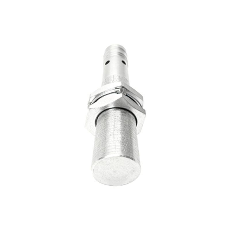
For optimal performance, correct installation is paramount. The sensor must be mounted securely to prevent vibration from altering the air gap. The sensing face should be aligned parallel to the gear face and centered on the tooth path. The gap between the sensor and the tooth tip must be set within the sensor's specified range, typically using a feeler gauge. Too large a gap causes signal dropout; too small a risk physical damage. Regular maintenance, though minimal, should involve checking the mounting integrity, cleaning the sensing face of any accumulated metallic debris, and verifying signal integrity with an oscilloscope or PLC diagnostics.
In conclusion, gear sensor proximity switches are a foundational technology for modern industrial measurement and control. They translate the simple mechanical motion of a rotating gear into actionable, reliable electronic data. By enabling precise speed monitoring, positional awareness, and critical safety functions, they enhance efficiency, protect capital equipment, and ensure the smooth, automated operation of countless machines that power our world. Their durability and simplicity make them a preferred solution where accuracy and dependability under tough conditions are essential.