Introduction to Proximity Sensor Control Circuits
Proximity sensors are essential components in modern automation and industrial systems, detecting the presence or absence of objects without physical contact. These sensors rely on electromagnetic fields, infrared light, or ultrasonic waves to sense targets, making them ideal for harsh environments where durability and reliability are critical. The control circuit of a proximity sensor is the backbone of its operation, converting detected signals into actionable outputs for machinery or control systems. Understanding this circuit diagram is key for engineers designing, troubleshooting, or optimizing automated processes. This article delves into the typical control circuit layout, explaining each component's role and how they integrate to ensure precise sensing and response.
Basic Components of a Proximity Sensor Circuit
A standard proximity sensor control circuit consists of several core elements. First, the sensor itself, which may be inductive, capacitive, or photoelectric, generates a signal when an object enters its detection range. This signal is typically weak and requires amplification through an operational amplifier or transistor stage. Next, a power supply unit provides stable voltage, often 12V or 24V DC, to the sensor and circuit. A relay or solid-state switch acts as the output device, triggering external loads like motors or alarms. Additionally, protection components such as diodes, resistors, and capacitors are included to prevent voltage spikes, noise interference, and ensure circuit longevity. Each part must be carefully selected based on the application's voltage, current, and environmental conditions.
Circuit Diagram Breakdown and Functionality
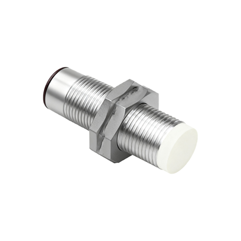
Examining a typical inductive proximity sensor circuit diagram reveals a structured flow. The sensor coil, when energized, creates an electromagnetic field. As a metal object approaches, eddy currents are induced, altering the coil's impedance. This change is detected by an oscillator circuit, which then sends a signal to a comparator. The comparator evaluates the signal against a preset threshold, and if exceeded, activates the output stage. In the output section, a transistor switches the relay coil, closing or opening contacts to control the load. For instance, in a 3-wire DC sensor, wires include positive, negative, and output lines, with the output often being an NPN or PNP transistor configuration. Diagrams also show snubber circuits or flyback diodes across inductive loads to suppress back-EMF, protecting sensitive components.
Wiring and Installation Considerations
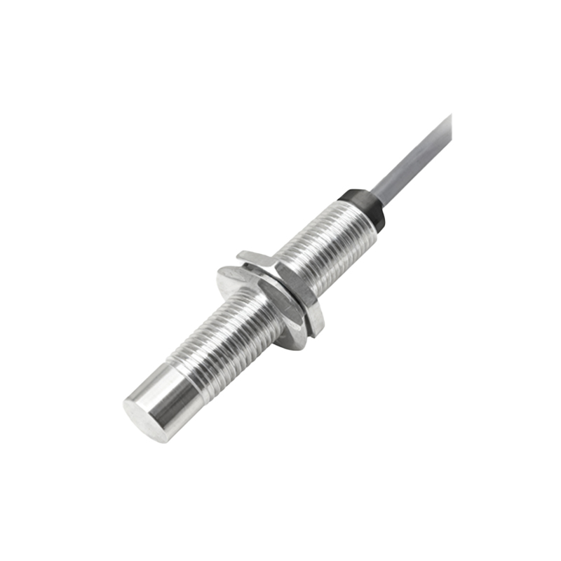
Proper wiring is crucial for proximity sensor circuit performance. Engineers must follow the manufacturer's diagram, ensuring correct polarity and grounding to avoid malfunctions. For 2-wire AC sensors, wiring is simpler but requires attention to load compatibility. In 3-wire DC setups, the brown wire typically connects to positive voltage, blue to negative, and black to the output load. Shielding cables may be necessary in high-noise environments to prevent false triggers. Additionally, installation factors like sensor mounting distance, material of the target object, and ambient temperature affect circuit behavior. Always test the circuit with a multimeter or oscilloscope to verify signal integrity and adjust sensitivity potentiometers if available for fine-tuning.
Common Applications and Practical Examples
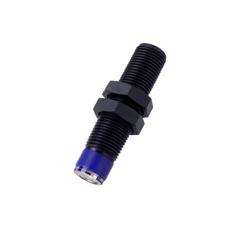
Proximity sensor control circuits are widely used across industries. In manufacturing, they enable object detection on conveyor belts, position sensing in robotic arms, and safety interlocks on machinery. For example, an inductive sensor circuit might detect metal parts in an assembly line, triggering a pneumatic actuator via a relay. In automotive systems, capacitive sensors in touchscreens or vehicle proximity alerts rely on similar circuits. Photoelectric sensors in packaging machines use light beams to count products, with circuits processing reflected signals. Each application tailors the basic diagram—adding timers, logic controllers, or communication modules like PLC interfaces for advanced automation. Understanding these variations helps engineers adapt circuits to specific needs.
Troubleshooting and Maintenance Tips
Even robust proximity sensor circuits can encounter issues. Common problems include false triggering, no output, or erratic behavior. Start by checking power supply levels and connections using the circuit diagram as a reference. Inspect for loose wires, corrosion, or physical damage to the sensor. If the output fails, test the relay or transistor with a load simulator. Noise interference often stems from unshielded cables near motors or high-voltage lines; repositioning or adding filters can resolve this. Regularly clean sensor faces to prevent debris buildup, and recalibrate as per operational changes. Documenting circuit modifications and keeping spare parts like fuses or relays on hand minimizes downtime in industrial settings.
Advancements and Future Trends
The evolution of proximity sensor circuits continues with smart technologies. Modern designs incorporate microcontrollers for digital signal processing, enabling features like self-diagnostics, adjustable sensing ranges, and IoT connectivity via protocols like IO