Introduction to Photoelectric Sensor Signal Lines
The signal line is the critical communication pathway for any photoelectric sensor, transmitting the detection state—typically a simple ON/OFF signal—to a controller like a PLC. When we specify a 12V signal line, we are defining both the operating voltage for the sensor's internal circuitry and the voltage level of the output signal it provides. This 12VDC standard is ubiquitous in industrial automation, favored for its balance of safety, compatibility with common power supplies, and reliable noise immunity compared to lower voltages. The signal line itself is usually a shielded cable containing at least three conductors: one for Vcc (12V), one for the output signal, and one for ground (0V). Proper selection and installation of this cabling are paramount, as they directly impact the sensor's reliability, response time, and longevity in the field. Engineers must consider not just the voltage rating, but the current-carrying capacity, environmental shielding, and connection integrity.
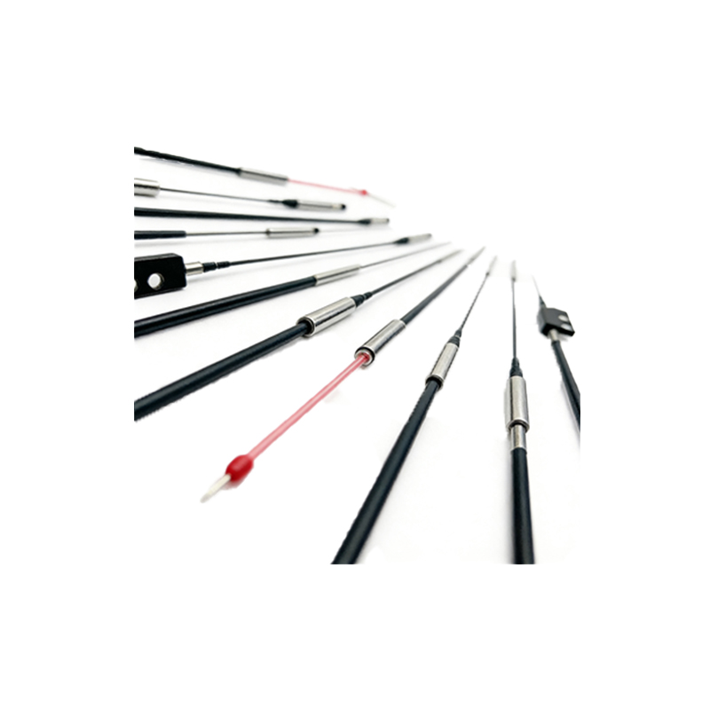
Wiring Configurations: Sourcing vs. Sinking
A fundamental concept when dealing with 12V photoelectric sensor outputs is the distinction between sourcing (PNP) and sinking (NPN) transistor configurations. This determines how the sensor's output switch interacts with the load and the common ground. A sourcing (PNP) sensor switches the positive 12V line to the load. In this setup, the load is connected between the sensor's output wire and ground (0V). When the sensor activates, it provides the 12V source to the load. Conversely, a sinking (NPN) sensor switches the ground path. Here, the load is connected between the 12V supply and the sensor's output wire. The sensor, when active, completes the circuit to ground. The choice between PNP and Sourcing is often dictated by regional conventions or the input type of the connected controller. Mismatching these configurations is a common installation error that results in a non-functional system.
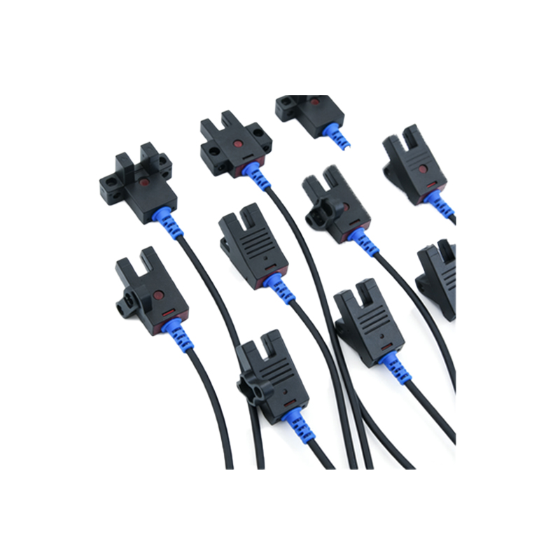
Output Types: Digital and Analog Signals
While the classic discrete ON/OFF (digital) output is most common, 12V signal lines can also carry analog or specialized signals. The digital output is straightforward: when the sensor detects an object, its internal transistor switches, changing the state on the signal line from 0V to approximately 12V (for a PNP type) or vice-versa. This is ideal for presence detection, counting, or positioning. Some sensors offer a push-pull output stage, which actively drives the line high or low, providing stronger noise immunity. For applications requiring measurement, such as detecting distance or transparency, sensors may provide an analog voltage output on the signal line. Here, the voltage varies proportionally between 0V and 12V based on the measured parameter. This 0-10V or 0-12V signal is then read by an analog input module on the controller.
Noise Immunity and Shielding Practices
Industrial environments are electrically noisy, with interference from motor drives, welding equipment, and radio transmissions. This noise can induce false signals on sensor lines, causing catastrophic errors in automation. The 12V level offers a higher signal-to-noise ratio than 5V systems, but proper shielding is non-negotiable. The signal cable should feature a braided or foil shield, which must be grounded at only one end—typically at the control panel—to prevent ground loops. For long cable runs exceeding 50 meters, using twisted pair wires within the cable is advisable to cancel out electromagnetic interference. In extreme noise environments, employing a dedicated conduit for sensor wiring, separate from AC power lines, is a best practice. Additionally, ensuring clean, stable 12V power from a regulated supply prevents voltage dips or ripple from affecting sensor performance.
Practical Installation and Troubleshooting Tips
Successful deployment begins with correct wire sizing. For most 12V sensor applications, a 18-22 AWG cable is sufficient. Always confirm the sensor's maximum output current (often 100-200mA) to ensure the wire and connected load can handle it. Use high-quality, corrosion-resistant connectors and secure cable grips at the sensor housing to prevent strain on internal terminals. During commissioning, use a digital multimeter to verify: 1) Steady 12V ±10% at the sensor's power terminals, 2) A clean switch between 0V and ~12V (or vice-versa) at the signal wire when the sensor is triggered. Common issues include incorrect PNP/NPN wiring, insufficient power supply current for multiple sensors, voltage drop over long wires, and damaged cable insulation. A systematic approach to verifying power, ground, and signal integrity resolves the majority of field failures.
Integration with PLCs and Control Systems
Integrating a 12V photoelectric sensor into a Programmable Logic Controller (PLC) system requires matching the sensor's output type with the PLC's input module. Most modern PLC digital input modules are designed to accept a wide range of voltages (e.g., 12-24VDC) and can be configured for either sourcing or sinking logic. The sensor's signal wire is connected to a specific input point on the module. The internal circuitry of the input module interprets the voltage presence (12V for ON, 0V for OFF) as a logic state (1 or 0) within the PLC program. For analog sensors, a specialized analog input module reads the precise voltage on the signal line and converts it to a digital value for processing. Proper grouping of sensor commons and careful attention to the PLC module's wiring diagram are essential to avoid back-feeding and ensure reliable operation.
Future Trends and Considerations
The role of the simple 12V signal line is evolving with Industry 4.0. While the fundamental electrical interface remains, sensors are increasingly becoming "smarter." IO-Link technology, for instance, can use the standard 3-wire 12V connection not just for the binary signal, but also for a digital communication channel. This allows for parameter configuration, advanced diagnostics, and process data transmission over the same wires. Furthermore, the demand for miniaturization continues, pushing for smaller connectors and cabling while maintaining performance. However, the 12VDC standard's robustness ensures its longevity in harsh industrial settings. Engineers must now consider not just the electrical characteristics of the signal line, but also its potential as a data highway for predictive maintenance and enhanced system intelligence.