Understanding the Nature of Inverter Drive Interference
Modern industrial automation heavily relies on the precise operation of both inverter drives (Variable Frequency Drives, VFDs) and proximity sensors. Inverter drives control motor speed and torque by generating Pulse Width Modulated (PWM) output signals. This process inherently creates high-frequency switching noise, rich in harmonics, which constitutes electromagnetic interference (EMI). Proximity sensors, particularly inductive and capacitive types, function by detecting changes in an electromagnetic field. They are inherently sensitive to external electromagnetic disturbances. The core of the interference problem lies in the fact that the high-frequency EMI generated by the inverter's switching transistors (IGBTs) can couple into the sensor's circuitry or its signal cables, corrupting the sensor's output signal. This can manifest as false triggering, failure to detect an object, or erratic and unstable switching behavior, leading to machine downtime and production defects.
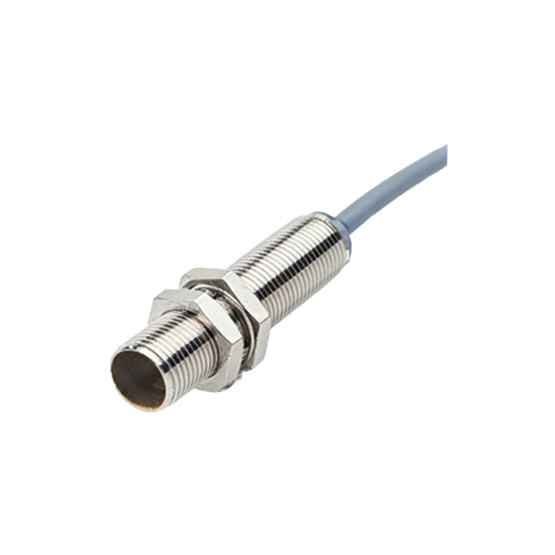
Primary Coupling Paths for Interference
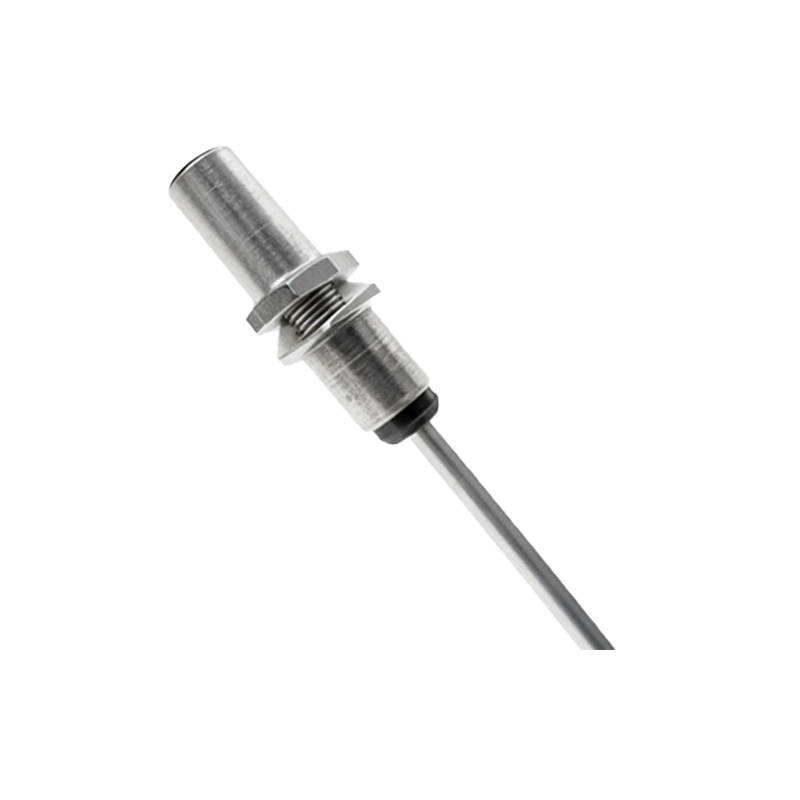
Interference typically reaches the proximity sensor through three main coupling paths. Conducted interference travels along shared power lines or grounding conductors. When the sensor and the inverter share a common power supply, the high-frequency noise can ride on the DC or AC power rails, directly infiltrating the sensor's power input stage. Radiated interference is emitted through the air from the inverter's power cables, especially the motor output cables which carry the high dv/dt PWM waveforms. These cables act as inefficient antennas, broadcasting EMI that can be picked up by the unshielded sensor or its wiring. Finally, capacitive or inductive coupling occurs when sensor signal cables are routed in close proximity to the inverter's power cables. The changing electric and magnetic fields from the power cables induce unwanted voltages and currents in the adjacent sensor lines, even without direct physical contact.
System Design and Installation Best Practices
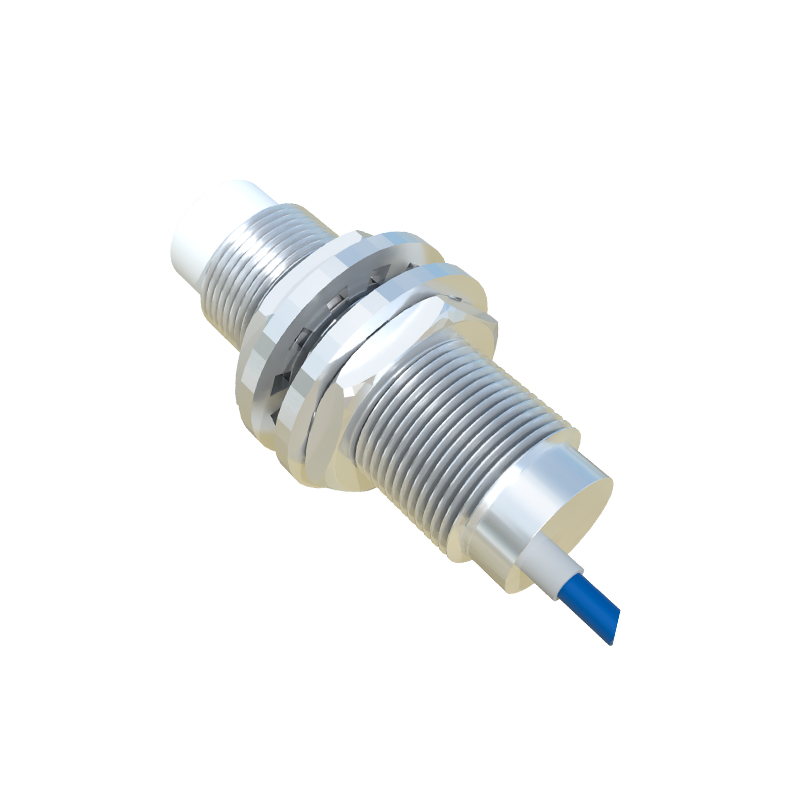
Effective mitigation begins with proper system design and installation. A fundamental rule is to maintain maximum physical separation between proximity sensor cables (especially signal and feedback lines) and inverter power cables. A minimum distance of 200mm is recommended, and crossing should be done at right angles if unavoidable. Using shielded cables for all sensor connections is non-negotiable. The shield must be a braided or foil type, and it must be grounded properly at the sensor end only, or at both ends using a low-impedance path, to prevent ground loops. The grounding point should be a clean, dedicated ground connection, ideally a star point, separate from the noisy ground of the inverter. Ferrite cores or clamps installed on sensor cables near the connection points can suppress high-frequency common-mode noise.
Component Selection and Filtering Solutions
Choosing the right components adds a layer of protection. Select proximity sensors with high electromagnetic compatibility (EMC) ratings, specifically those certified for use in industrial environments with heavy RFI/EMI. Sensors with DC models that include built-in surge protection and filtering are preferable. For the inverter drive system, installing an AC line reactor or a sinusoidal filter on the output side significantly reduces the harmonic content and dv/dt of the waveform going to the motor, thereby reducing emitted EMI at its source. For severe cases, placing the entire inverter in a shielded metallic enclosure can contain radiated emissions. Additionally, using isolated sensor signal conditioners or interfaces can break ground loops and provide clean, amplified signals to the controller.
Diagnosis and Troubleshooting Procedures
When interference is suspected, a systematic approach is required. First, verify the symptoms: intermittent operation correlated with motor speed changes is a key indicator. Use an oscilloscope with a high-frequency probe to inspect the sensor's output signal line. Look for superimposed high-frequency noise or ringing on the DC signal. A portable spectrum analyzer can help identify the dominant interference frequencies. A practical test is to temporarily power the proximity sensor from an independent, battery-powered DC supply. If the erratic behavior ceases, conducted interference via the power line is likely. Similarly, rerouting the sensor cable away from all power lines can diagnose radiated or coupled interference. Always check the integrity of cable shields and ground connections, as a single broken shield strand can render the protection ineffective.
Advanced Mitigation and System Integration
For complex or mission-critical systems, advanced strategies may be necessary. Implementing fiber-optic communication for sensor signals provides complete immunity to EMI, though it adds cost. Using analog sensors with 4-20mA current-loop outputs instead of digital switches offers greater noise immunity due to the higher signal energy. In programmable logic controller (PLC) systems, implementing software debounce filters or delay timers can help the controller ignore brief, noise-induced false pulses, though this is a last-resort software fix