Introduction to Photoelectric Sensor Aluminum Housings
The aluminum housing of a photoelectric sensor serves as a critical component, providing robust protection and ensuring reliable performance in industrial environments. These housings are engineered to shield sensitive internal electronics—such as the emitter, receiver, and signal processing circuitry—from external hazards including dust, moisture, mechanical impact, and electromagnetic interference. The choice of aluminum as a material is deliberate, leveraging its excellent strength-to-weight ratio, superior thermal conductivity for heat dissipation, and inherent corrosion resistance. A well-designed housing not only extends the operational lifespan of the sensor but also facilitates easier integration into automated systems. Understanding the schematic representation of this housing is fundamental for engineers involved in selection, installation, and maintenance, as it details how physical protection aligns with the sensor's functional architecture.
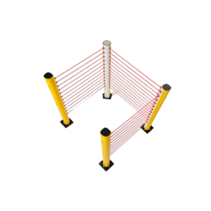
Key Components in the Schematic Diagram
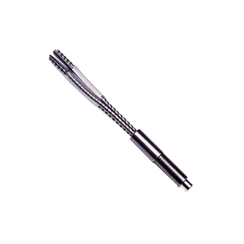
A schematic diagram for a photoelectric sensor's aluminum housing typically illustrates several key physical and interface elements. The primary structure is the main aluminum alloy enclosure, often depicted in cross-section to show its walls, mounting threads or brackets, and the sealing gasket channels. The diagram precisely indicates the positions and dimensions of the optical windows or lenses, which are made of specialized glass or polycarbonate and are hermetically sealed to the aluminum body. It also details the cable entry points, usually featuring gland nuts or M12 connectors, and their associated sealing mechanisms. Vent plugs or membranes for pressure equalization might be shown if the sensor is designed for environments with significant temperature fluctuations. Furthermore, the schematic includes reference to internal mounting points or bosses that secure the PCB (Printed Circuit Board) assembly in place, ensuring the optical alignment remains stable under vibration.
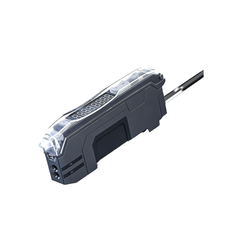
Sealing and Environmental Protection Design
The core of the housing schematic revolves around its ingress protection (IP) rating design. The diagram meticulously outlines the sealing strategy to achieve ratings such as IP67 or IP69K. This involves the depiction of O-rings or flat gaskets made from materials like NBR or FKM, seated in precisely machined grooves around the lens cover and cable glands. The lens-to-housing seal is critical, often using a combination of adhesive and compressive gasketing to prevent fogging and liquid ingress. The schematic may also show the use of potting compounds around internal wire terminations or even over the entire PCB for additional protection against humidity and condensation. For aluminum housings in hygienic or washdown applications, the schematic emphasizes smooth, crevice-free external surfaces and the use of electropolishing or specific anodization coatings to meet sanitation standards.
Thermal Management and Electrical Shielding
Aluminum's high thermal conductivity is a key feature highlighted in the housing schematic. The diagram often uses thermal flow lines or notes to illustrate how heat generated by the sensor's internal electronics (especially the emitter LED) is transferred through the housing walls and dissipated into the surrounding air or mounting surface. This passive cooling is vital for maintaining stable wavelength output and circuit reliability. Simultaneously, the schematic addresses electromagnetic compatibility (EMC). It may indicate the use of conductive seals at joints, the integration of a shielded cable gland, or the application of a chromate conversion coating on the aluminum interior to enhance grounding continuity. This ensures the housing acts as a Faraday cage, protecting the sensor from external radio frequency interference and preventing it from emitting electromagnetic noise.
Mechanical Integration and Mounting Features
The schematic provides essential data for mechanical installation. It details standardized mounting interfaces, such as threaded barrels (e.g., M18, M30), or bracket fixing holes with specific pitch circle diameters. Tolerances for these features are clearly annotated to ensure proper fit with industry-standard mounting accessories. The diagram also shows anti-rotation flats or keyways that prevent the sensor from turning after installation, crucial for maintaining precise optical alignment. For sensing range adjustment, the schematic might illustrate the housing design for sensors with built-in potentiometers or teach-in buttons, showing the sealed rubber caps or magnetic actuation points that allow configuration without compromising the seal. Stress analysis notes may be included, indicating areas reinforced to withstand tightening torques or accidental impacts.
Material Specifications and Surface Treatment
Beyond the basic shape, the schematic diagram includes critical callouts for material specifications and surface finishes. The aluminum alloy grade (e.g., 6061 or 5083) is specified, along with any heat treatment (T6 temper) to achieve the desired mechanical properties. Surface treatments are detailed, such as anodizing (type and thickness, e.g., 20µm hard anodize) for wear and corrosion resistance, or powder coating for specific color coding and additional chemical protection. These treatments are not merely cosmetic; they are integral to the housing's durability. The schematic specifies which surfaces are treated and which remain bare for optimal electrical grounding. Notes on chemical passivation processes to meet RoHS or other regulatory standards are also commonly found in this section of the documentation.
Interpreting the Schematic for Maintenance and Troubleshooting
For maintenance personnel, the housing schematic is an invaluable troubleshooting tool. It allows technicians to identify potential failure points, such as a compromised seal at a specific gland or a cracked lens retainer. By understanding the assembly sequence shown in an exploded-view schematic, disassembly and reassembly for repair can be performed correctly without damaging the seals. The diagram helps in verifying the correct replacement part numbers for O-rings, lens covers, or entire housing halves. Furthermore, it aids in diagnosing issues like internal condensation (pointing to a failed vent membrane) or intermittent operation due to poor grounding (highlighting the importance of clean, untreated mounting surfaces). A thorough grasp of this schematic ensures that the sensor's integrity is maintained throughout its service life.