Understanding Photoelectric Sensors in HVAC Systems
Photoelectric sensors are critical components in modern air conditioning systems, primarily used for safety and operational control. These sensors function by emitting a beam of light, typically infrared, and detecting its reflection or interruption. In HVAC applications, they are often employed in air handlers, ductwork, and outdoor units to monitor airflow, detect blockages, or ensure filter positioning. The core principle involves a transmitter and a receiver; when the light path is obstructed, the sensor triggers a response in the control system. This mechanism is vital for preventing equipment damage, optimizing energy efficiency, and ensuring safe operation by halting the system if hazardous conditions, like restricted airflow, are detected. Understanding this operational basis is essential before proceeding to the wiring aspects, as it informs the connection logic and system integration requirements.
Components and Specifications Overview
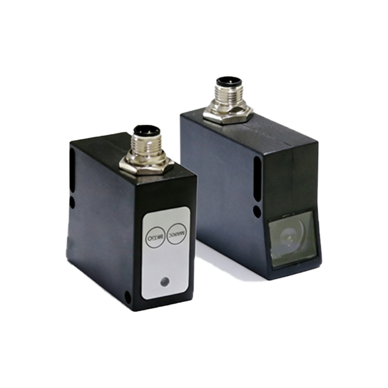
A standard photoelectric sensor assembly for air conditioning includes several key parts. The sensor itself typically consists of a plastic or metal housing containing the infrared LED (light-emitting diode) and a phototransistor or photodiode receiver. Accompanying components are the mounting bracket, lens covers for dust protection, and a cable or connector interface. Specifications vary by model but commonly include parameters such as sensing distance (often 1-5 meters for HVAC uses), response time, light source wavelength, and output type—usually digital (PNP/NPN) or analog. Power requirements are typically low-voltage DC, ranging from 12V to 24V, aligning with standard control circuit voltages in AC units. It is crucial to consult the manufacturer's datasheet for exact ratings, as incorrect voltage application can lead to sensor failure or system malfunctions.
Standard Wiring Diagram and Connections
The wiring configuration for a photoelectric sensor in an air conditioning system follows a systematic approach. A typical three-wire sensor includes wires for power supply, ground, and output signal. For a common NPN-type sensor: connect the brown wire to the positive DC supply (e.g., +24V from the control board), the blue wire to the common ground (0V), and the black wire to the input terminal of the controller or relay. In some models, a white wire may be present for complementary output. The sensor's output acts as a switch, closing or opening the circuit based on light detection. For instance, in an airflow monitoring setup, if the sensor beam is uninterrupted (indicating proper airflow), the output circuit closes, sending a signal to permit compressor operation. Conversely, an interrupted beam opens the circuit, signaling the control board to shut down the fan or entire unit. Always ensure connections are secure and insulated to prevent short circuits.
Integration with Control Systems
Integrating the photoelectric sensor into the air conditioner's control system requires aligning its output with the unit's logic. Most modern HVAC systems use a microcontroller or programmable logic controller (PLC) to process sensor inputs. The sensor's output wire is connected to a designated digital input port on the controller. Programming within the controller then defines the response—such as activating an alarm, adjusting fan speed, or initiating a shutdown sequence. For example, in a filter monitoring application, the sensor positioned across the filter track sends a signal when a filter is missing or incorrectly installed, prompting an alert on the user interface. It is advisable to include a pull-up or pull-down resistor in the circuit if required by the controller design to ensure stable signal reading. Testing integration with a multimeter or oscilloscope can verify signal integrity before full system commissioning.
Installation Best Practices and Safety
Proper installation is paramount for reliable sensor operation. Begin by selecting an appropriate location free from obstructions, direct sunlight, or excessive vibration, which could cause false triggers. Mount the sensor and its reflector (if used) securely using provided brackets, ensuring precise alignment for consistent beam transmission. Maintain recommended clearance distances from metal surfaces or other electronic devices to avoid interference. During wiring, adhere to electrical safety standards: disconnect power to the AC unit, use wire strippers for clean connections, and employ conduit or cable ties for organized routing. After connections, perform a functional test by simulating beam interruption (e.g., with a cardboard piece) to confirm the system responds correctly. Regular maintenance, such as cleaning lens surfaces from dust buildup, ensures long-term accuracy and prevents nuisance faults.
Troubleshooting Common Wiring Issues
Several common issues may arise with photoelectric sensor wiring in air conditioning systems. If the sensor fails to activate, first check power supply voltage with a multimeter at the sensor terminals to confirm it meets specifications. Loose or corroded wire connections are frequent culprits—inspect terminals for tightness and cleanliness. Incorrect wiring polarity, especially swapping positive and ground wires, can damage the sensor; verify wire colors against the diagram. Environmental factors like condensation or extreme temperatures might affect performance, so ensure the sensor is rated for the operating conditions. If the output signal is erratic, use an oscilloscope to check for noise interference, and consider adding shielded cables or ferrite cores. Consulting the system's error codes and sensor datasheet for diagnostic indicators can expedite resolution, avoiding unnecessary part replacements.