Understanding the Proximity Sensor with Indicator Light
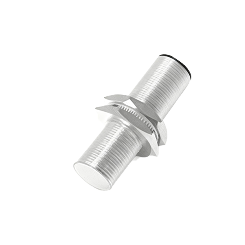
A proximity sensor with an integrated indicator light is a crucial component in industrial automation, providing both object detection and immediate visual feedback. This dual functionality allows operators and maintenance personnel to quickly verify the sensor's operational status and detect the presence of a target without relying solely on the control system's interface. The indicator light, typically an LED, illuminates when the sensor detects an object within its sensing range. This feature is invaluable for troubleshooting, commissioning, and routine system checks. The sensor itself operates on the principle of electromagnetic induction (for inductive types) or optical reflection (for photoelectric types), generating a discrete electrical signal upon detection. The wiring process must correctly integrate both the sensing output and the indicator circuit, which are often internally linked but require proper external power and load connections.
Essential Components and Pre-Wiring Checklist
Before beginning the wiring process, gather all necessary components and perform safety checks. You will need the proximity sensor itself, a suitable DC power supply (commonly 10-30V DC for industrial sensors), the load (such as a PLC input, relay coil, or contactor), and appropriate cabling. Always consult the sensor's datasheet for its specific voltage rating, current consumption, output type (PNP-sourcing or NPN-sinking), and wire color code. Standard color coding often includes brown for positive (+V), blue for negative (0V or common), and black for the switched output signal. The indicator light is usually internally connected to the output circuit. Ensure the power supply is disconnected and locked out (LOTO procedure) before handling any wires. Verify that the sensor's sensing distance and target material are appropriate for the application.
Wiring a Three-Wire DC Proximity Sensor (PNP Configuration)
The three-wire DC sensor is the most common type. For a PNP (sourcing) sensor, follow this procedure. First, connect the brown wire from the sensor to the positive terminal (+V) of your DC power supply. Second, connect the blue wire from the sensor to the negative terminal (0V or common) of the power supply. The black wire is the signal output. Connect this black wire to one terminal of your load (e.g., the PLC input channel). The other terminal of the load must then be connected back to the power supply's negative (0V) rail to complete the circuit. In this configuration, when the sensor detects an object, it internally connects the black output wire to the positive supply, "sourcing" current through the load to the common negative. The internal indicator LED will illuminate simultaneously with this output activation.
Wiring a Three-Wire DC Proximity Sensor (NPN Configuration)
For an NPN (sinking) sensor, the wiring differs slightly. Connect the brown wire to the positive supply (+V) and the blue wire to the negative supply (0V), as before. The critical difference lies in the output connection. Connect the black output wire from the sensor to one terminal of your load. However, the other terminal of the load must now be connected to the positive supply (+V) rail. When an object is detected, the NPN sensor internally connects the black output wire to the negative common, "sinking" current from the load, which is now connected to positive. This completes the circuit, activating the load and the internal indicator light. It is vital to match the sensor's output type (PNP/NPN) with the input requirements of your controller to avoid malfunction.
Integrating the Sensor into a Control System
Once the basic power and output wiring are complete, integration into the broader control system is key. The load connected to the sensor's output is typically a digital input module on a Programmable Logic Controller (PLC). The sensor acts as a binary input device, telling the PLC whether a part is present, a machine is in position, or a safety gate is closed. The indicator light provides immediate local confirmation of this state. For complex systems, consider wiring the indicator circuit separately if a dedicated diagnostic signal is required, though this is less common. Always use conduit, cable ducts, or strain relief to protect the wiring from physical damage and electrical interference in industrial environments.
Troubleshooting and Verification of Operation
After wiring, apply power and perform functional tests. If the indicator light does not behave as expected, begin troubleshooting. First, verify power supply voltage at the sensor terminals with a multimeter. If the indicator is permanently on, check for a target object within the sensing range or sensor contamination. If the indicator is off and unresponsive, check for loose connections, incorrect wiring (