Introduction to Photoelectric Sensor Signal Issues
In industrial automation, photoelectric sensors are critical components for detecting the presence, absence, or position of objects. A common and disruptive problem encountered by maintenance engineers and technicians is the complete absence of signal feedback from these sensors. When a photoelectric sensor fails to provide an output signal, it can halt production lines, cause machine faults, and lead to significant downtime. This guide provides a systematic, engineer-level approach to diagnosing and resolving the root causes of "no signal" failures in photoelectric sensors. Understanding the sensor's operating principle—whether through-beam, retro-reflective, or diffuse—is the first step in effective troubleshooting, as each type has unique failure modes.
Primary Power Supply and Wiring Checks

The most fundamental step is to verify the integrity of the power supply and electrical connections. Begin by using a multimeter to confirm that the sensor is receiving the correct voltage at its terminals, as specified in the datasheet (e.g., 10-30 VDC). Check for loose connections, corroded terminals, or damaged cables, especially at junction boxes and cable glands. Inspect the wiring against the manufacturer's diagram, ensuring the brown wire (typically +V), blue wire (typically 0V/Common), and black wire (typically output) are correctly connected to the controller or PLC. A common oversight is incorrect polarity or a floating/disconnected load wire. Also, verify that the load (e.g., PLC input, relay coil) is within the sensor's rated switching capacity and is functioning correctly.
Optical Path and Alignment Inspection
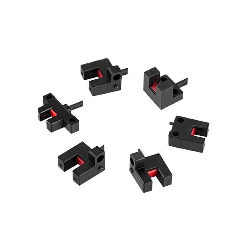
For through-beam and retro-reflective sensors, a blocked or misaligned optical path is a frequent culprit. Physically inspect the line-of-sight between the emitter and receiver (or reflector). Look for accumulated dust, dirt, oil mist, or physical obstructions like stray packaging material. Carefully clean the lenses of both the transmitter and receiver using appropriate materials. For alignment, use the sensor's built-in alignment indicator (often an LED) or follow the manufacturer's procedure. Even minor misalignment, caused by vibration or mechanical impact, can cause signal loss. For diffuse sensors, ensure the target object is within the specified sensing range and has adequate reflectivity for the sensor's configured sensitivity.
Sensitivity Adjustment and Configuration
An incorrectly set sensitivity potentiometer can prevent the sensor from detecting the target. If the threshold is set too high, the sensor may not register a valid object. If set too low, it might be saturated by background reflection or ambient light. Access the sensitivity adjustment screw or button according to the manual. For a through-beam sensor, place the target object in the beam and adjust the sensitivity until the output indicator LED activates reliably. For diffuse sensors, use the actual target at the required distance. Many modern sensors feature teach-in functions or push-button configuration; ensure these have been performed correctly for the application. Also, verify that any DIP switches for operating mode (e.g., light-on/dark-on) are set as intended.
Environmental and Electrical Interference
Harsh environmental conditions can lead to signal failure. Excessive ambient light, such as direct sunlight or strobe lights, can blind the receiver. Consider using a sensor with modulated infrared light or installing a physical shade. Electrical noise from motors, variable frequency drives (VFDs), or welding equipment can interfere with the sensor's internal circuitry or corrupt the output signal. Ensure proper grounding practices, use shielded cables with the shield grounded at one end only (typically the control panel end), and separate sensor cables from power lines. Also, check for voltage spikes or sags on the supply line that could reset or damage the sensor.
Sensor Diagnostics and Functional Testing
Utilize the sensor's built-in diagnostic indicators. Most sensors have a power (green) LED and a signal (yellow or orange) LED. A lit power LED confirms voltage is present. The behavior of the signal LED indicates the sensor's detection state. Consult the manual to interpret blinking patterns, which often indicate specific faults like overload, short-circuit, or contamination. Perform a basic functional test by bypassing the control logic. Temporarily connect the sensor output directly to a known-good indicator lamp or a multimeter set to measure voltage. Manually trigger the sensor (e.g., block the beam). If the output switches correctly in this isolated test, the issue may lie downstream in the PLC input module or wiring.
Mechanical Damage and Component Failure
Conduct a thorough physical inspection of the sensor housing, lens, and connector. Look for cracks, deep scratches on the lens, or signs of impact. Internal component failure is possible, especially due to prolonged exposure to extreme temperatures, humidity, or corrosive chemicals. While not always field-repairable, knowing the expected lifespan under operating conditions is valuable. If all previous checks are conclusive and the sensor fails the isolated functional test, the most likely cause is an internal failure of the emitter, receiver, or output switching transistor. At this point, replacement with a verified working unit is the most efficient solution.
System Integration and PLC Interface Verification
If the sensor tests correctly in isolation, the problem may be in the interface with the Programmable Logic Controller (PLC) or other control system. Verify that the PLC input card corresponding to the sensor is operational. Check the input LED on the PLC card. Use the PLC programming software to monitor the real-time status of the input bit. Ensure the sensor's output type (NPN sinking or PNP sourcing) is compatible with the PLC input type. A common mismatch, such as connecting an NPN sensor to a sourcing input, will result in no signal. Also, inspect the wiring from the sensor output to the PLC terminal for breaks or poor connections.
Preventive Maintenance and Best Practices
Preventing no-signal failures is more efficient than troubleshooting them. Establish a regular preventive maintenance schedule. This includes periodic cleaning of lenses and housings, checking and re-tightening electrical connections, verifying alignment in high-vibration areas, and auditing sensitivity settings. Maintain a log of sensor performance and replacements. Consider implementing condition monitoring where feasible. Always keep critical spares in stock, and ensure personnel are trained on the specific sensor models used in the facility. Proper sensor selection at the design stage for the specific environment (e.g., high-temperature, washdown models) is the ultimate preventive measure.