Understanding Proximity Sensors in Vibratory Systems
Proximity sensors are indispensable components in modern vibratory feeder systems, serving as the critical "eyes" for part detection and process control. Unlike mechanical limit switches, these non-contact electronic devices detect the presence or absence of a target object—typically a component on the feeder bowl track—without physical touch. In vibratory applications, inductive proximity sensors are predominantly used due to their reliability in detecting metallic parts. The core principle involves an oscillator generating a high-frequency electromagnetic field from the sensor's face. When a metallic object enters this field, eddy currents are induced, causing a change in the oscillation amplitude. This change is detected by the sensor's circuitry, which subsequently triggers a solid-state output signal to the feeder's controller. This seamless detection enables precise control over part feeding, sorting, and orientation sequences, forming the backbone of automated assembly lines.
Key Selection Criteria for Optimal Performance
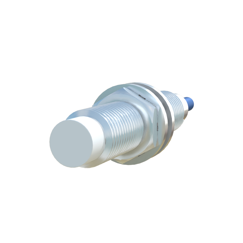
Selecting the right proximity sensor for a vibratory feeder is paramount for system reliability. The first consideration is the sensing distance, which must account for the gap between the sensor face and the target part, including any potential vibration-induced variations. A general rule is to choose a sensor with a nominal sensing range 20-30% greater than the maximum required gap. Secondly, the sensor's housing material and shape are critical. Stainless steel or nickel-plated brass housings offer superior resistance to mechanical wear from potential part collisions and exposure to industrial cleaning agents. Cylindrical threaded barrels (e.g., M8, M12, M18) are standard for easy mounting. The output type must match the controller's input; PNP (sourcing) and NPN (sinking) are common, with 2-wire DC and AC models also available for specific setups. Finally, frequency response, or the sensor's switching speed, must be high enough to detect parts moving at the feeder's maximum feed rate without missing any objects.
Installation Best Practices and Mounting Techniques
Proper installation is crucial to mitigate the challenges posed by continuous vibration. Sensors must be securely mounted using locking nuts on their threaded barrels to prevent loosening. Anti-vibration mounts or shock-absorbing washers can be employed in high-amplitude applications. The sensing face should be positioned parallel to the target surface for consistent detection, maintaining the recommended gap as per the sensor's data sheet. It is vital to ensure that no other metallic objects, like the feeder bowl itself or mounting brackets, are within the sensor's nominal sensing range, as this can cause false triggering. Shielding is another key factor; shielded (flush-mountable) sensors are preferred when mounted in metal, as their electromagnetic field is focused forward, minimizing side interference. For wiring, use flexible, shielded cables with strain relief to withstand constant motion and reduce electrical noise interference, which is common in environments with vibratory motors and solenoids.
Common Challenges and Troubleshooting Procedures
Even with correct selection and installation, issues can arise. A frequent problem is false triggering or failure to detect. This can stem from accumulated debris, oil, or metal dust on the sensor face, which must be cleaned regularly. Incorrect sensing distance due to loosened mounting or part position variation is another common culprit. Electrical issues include voltage fluctuations from the power supply or electrical noise interference from nearby motors, which can be resolved by using stable, regulated power supplies and proper cable shielding. If a sensor fails intermittently, checking the load current against the sensor's maximum rating is essential to prevent overload. For persistent problems, swapping the sensor with a known-working unit from another station is a quick diagnostic step to isolate whether the fault lies with the sensor, wiring, or the controller's input module.
Advanced Features and Integration with Control Systems
Modern proximity sensors offer features that enhance vibratory feeder intelligence. Analog output sensors provide a continuous signal proportional to the distance to the target, useful for monitoring part jams or track fullness. Sensors with IO-Link capability enable digital communication, allowing for remote parameter setting, condition monitoring, and diagnostic data readback directly into the PLC. This facilitates predictive maintenance by tracking operational hours or temperature. For challenging applications with very small or non-ferrous metal parts, capacitive or specialized high-frequency inductive sensors may be employed. Integrating sensor signals with the feeder controller and the broader PLC or robotic system allows for complex sequencing, such as stopping the feeder when a downstream machine is busy or activating a reject mechanism when a misoriented part is detected, creating a fully synchronized and efficient automated cell.