Understanding Slot Type Photoelectric Sensors
Slot type photoelectric sensors, often referred to as through-beam sensors in a compact form, consist of a built-in emitter and receiver facing each other across a narrow gap or "slot." These devices are widely utilized in industrial automation for detecting the presence, absence, or position of objects that pass through this slot. Common applications include counting, jam detection, and edge guiding in material handling, packaging, and printing machinery. Their self-contained design simplifies installation compared to separate emitter-receiver pairs, as alignment is inherently fixed by the sensor housing. The slot's width and depth are critical parameters, determining the size and type of objects that can be reliably detected. Typically, these sensors operate by emitting infrared or visible light from one side; an object interrupting the light beam as it passes through the slot causes the receiver to trigger a switching output. This straightforward principle makes them highly reliable for high-speed applications where precision is paramount. Understanding the mechanical and optical characteristics of the slot is the first step toward correct implementation in any control system.
Essential Wiring Components and Tools
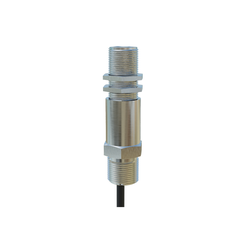
Proper wiring is fundamental to ensuring the sensor functions correctly and integrates seamlessly with programmable logic controllers (PLCs) or other control devices. For most industrial slot type photoelectric sensors, you will typically need a DC power supply (commonly 12-24V DC), the sensor itself, and connecting cables. The sensor usually features a cable or connector with several cores: typically, a brown wire for positive voltage supply (+V), a blue wire for negative or common (0V), and a black wire for the output signal (often NPN or PNP transistor output). Some models may include additional wires for diagnostic functions or complementary outputs. Essential tools include wire strippers, crimping tools for terminal connectors, a multimeter for voltage and continuity checks, and possibly a small screwdriver for terminal blocks. Always refer to the specific sensor's datasheet for the exact pinout and voltage ratings, as variations exist between manufacturers and models. Safety precautions, such as ensuring power is off during wiring and following local electrical codes, are mandatory to prevent equipment damage or personal injury.
Step-by-Step Wiring Procedure
Begin by disconnecting all power sources to the control panel or machine where the sensor will be installed. Identify the sensor's cable leads according to the manufacturer's documentation. For a standard three-wire DC sensor, connect the brown wire to the positive terminal of your DC power supply (e.g., +24V). Connect the blue wire to the negative or common terminal (0V). The black output wire should be connected to the input channel of your PLC or relay. If using an NPN output (sinking), the black wire will switch the load to common (0V); for a PNP output (sourcing), it switches to positive. Ensure all connections are secure using appropriate terminals or connectors. For sensors with built-in connectors, mate them with the corresponding receptacle on the sensor or junction box. After wiring, visually inspect for any loose strands or potential short circuits. Before applying power, double-check that the voltage matches the sensor's specifications. Once powered, many slot sensors have an indicator LED that illuminates when the beam is unobstructed, providing immediate visual feedback on operational status.
Configuration and Alignment Tips
While slot type sensors are pre-aligned, fine-tuning may be necessary for optimal performance, especially in challenging environments. After wiring, ensure the sensor is mounted securely so that objects pass cleanly through the slot without physical contact, which could cause damage. Adjust the sensor's sensitivity if it features a potentiometer or teach-in function; this helps compensate for environmental factors like dust, ambient light, or varying object colors. For transparent or highly reflective objects, increasing sensitivity might be required. Conversely, in dusty conditions, reducing sensitivity can prevent false triggers. Use the sensor's status LED as a guide during alignment: it should switch states reliably when a test object passes through. If the sensor has a light-on/dark-on mode selector switch, set it according to your control logic needs (e.g., output active when beam is blocked vs. unblocked). Remember that slot depth affects the sensing distance; ensure objects fully interrupt the beam across the slot's width for consistent detection.
Troubleshooting Common Wiring Issues
If the sensor fails to operate after wiring, systematic troubleshooting is essential. First, verify power supply voltage at the sensor terminals using a multimeter; incorrect polarity or voltage can prevent operation. Check the indicator LED: if it is off, power may not be reaching the sensor; if it is constantly on or off regardless of object presence, wiring or configuration may be incorrect. Ensure the output wire is connected to the correct PLC input and that the input is correctly configured (sinking vs. sourcing). For intermittent operation, inspect wiring for loose connections or damaged cables, especially at strain relief points. Electrical noise in industrial environments can sometimes cause erratic behavior; using shielded cables and grounding the shield at one end can mitigate this. If the sensor triggers without an object, ambient light interference might be the cause; some sensors have a modulated light source to resist such interference—ensure this feature is enabled if available. Consulting the sensor's manual for specific error indicators or diagnostic outputs can expedite resolution.
Importance of Video Guidance for Installation
A detailed wiring video serves as an invaluable visual aid, complementing technical manuals by demonstrating practical steps in real-time. For slot type photoelectric sensors, a video can clearly show cable routing, proper termination techniques, and the exact sequence of connections, reducing the risk of human error. It can illustrate how to handle different connector types, such as M8 or M12 connectors, which are common in sensor technology. Visual learners particularly benefit from seeing the indicator LED behavior during power-up and object detection. Furthermore, a video can showcase best practices for mounting the sensor to avoid mechanical stress on cables and ensure the slot remains unobstructed. For complex systems involving multiple sensors or networking, video tutorials can explain daisy-chaining or parallel wiring configurations. Always ensure any video reference is from a reputable source, such as the manufacturer or certified trainers, to guarantee accuracy and adherence to safety standards.