Introduction to Photoelectric Sensor Wiring
Photoelectric sensors are indispensable components in modern industrial automation, playing a critical role in object detection, positioning, and counting. Their operation hinges on precise electrical connections. A correct wiring setup is paramount for ensuring sensor reliability, safety, and optimal performance within a control system. This guide provides a comprehensive collection of wiring diagrams and essential knowledge for engineers and technicians. Understanding the fundamental wiring principles prevents malfunctions, protects equipment, and streamlines the installation and maintenance process across various applications.
Understanding Sensor Output Types

Before examining specific diagrams, it's crucial to identify the sensor's output type, as this dictates the wiring configuration. The two primary categories are discrete (digital) outputs and analog outputs. Discrete outputs are most common and are further divided into several key types. A PNP (sourcing) output switches the positive voltage to the load when activated. Conversely, an NPN (sinking) output switches the negative side (ground) to the load. Relay contact outputs provide physical isolation and can switch AC or DC loads independently of the sensor's supply voltage. Finally, push-pull (complementary) outputs combine PNP and NPN transistors, offering flexibility for connecting to either sinking or sourcing inputs. Always consult the sensor's datasheet to confirm its specific output configuration before proceeding with any wiring.
Standard 3-Wire and 4-Wire DC Sensor Wiring
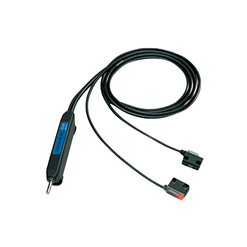
The majority of modern photoelectric sensors utilize a 3-wire DC configuration. This setup typically involves a brown wire for the positive supply voltage (e.g., +24V DC), a blue wire for the negative supply or common (0V), and a black wire for the switched output signal. For a PNP sensor, the black wire provides +V when the sensor is active. For an NPN sensor, the black wire provides a path to 0V when active. A 4-wire sensor often includes an additional output wire, usually white or gray, providing a complementary signal (e.g., normally-open and normally-closed outputs). The wiring diagram must clearly show the connection to the power supply and the load (e.g., a PLC input module, relay coil, or indicator lamp). Proper fusing and the use of shielded cables for noise immunity in electrically noisy environments are standard best practices illustrated in these diagrams.
Wiring for 2-Wire AC/DC Sensors
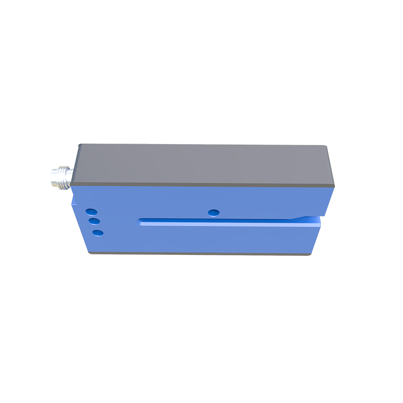
Two-wire sensors, often used in simpler applications, are wired in series with the load and the power supply. They function similarly to a switch. These sensors can be designed for AC or DC voltage. In an AC circuit, the two wires connect directly to the AC source and the load, with no polarity concerns. In a DC circuit, polarity must be observed. A key consideration with 2-wire sensors is the residual current or voltage drop across the sensor when in the "off" state, which must be compatible with the connected load's minimum operating requirements. Diagrams for this type emphasize the series connection and often include notes on ensuring the leakage current does not inadvertently activate sensitive PLC inputs.
Connecting to Programmable Logic Controllers (PLCs)
Integrating photoelectric sensors with PLCs is a fundamental task. The wiring method depends entirely on whether the PLC input module is designed for sinking (NPN) or sourcing (PNP) signals. For a sinking input module (common to positive), a PNP sensor's output is connected to the input point, completing the circuit to the module's common. For a sourcing input module (common to negative), an NPN sensor is used. Incorrect pairing can lead to non-operation or potential damage. Detailed diagrams show the complete circuit path from the sensor's power supply, through the sensor's output transistor, into the PLC input terminal, and to the internal opto-isolator, highlighting the correct matching of sensor and PLC input types.
Wiring Diagrams for Special Functions
Advanced photoelectric sensors offer functions like teach-in (programming), output inversion, or timer modes, which may require specific wiring. For instance, some sensors have separate teach-in wires that must be momentarily connected to a voltage or ground to enter programming mode. Others feature separate wires for enabling/disabling the output or selecting between light-on/dark-on operation. Diagrams for these sensors include these auxiliary connections, clearly labeling them as control signals rather than power or primary output wires. They often show a momentary switch connected to these pins to initiate the special function.
Safety and Practical Wiring Tips
Beyond the diagrams, practical implementation requires adherence to safety and performance standards. Always disconnect power before wiring. Use the correct wire gauge for the current load. Employ cable glands or strain relief to prevent wire pull-out. For long cable runs or noisy environments, use twisted-pair shielded cables, connecting the shield to ground at only one end (typically the control panel end) to prevent ground loops. Label all wires clearly at both ends. Finally, after wiring, perform a systematic check: verify power supply voltage, confirm sensor indicator LED operation, and test the output signal with a multimeter or the connected control system before placing the system into full operation.