Introduction to Photoelectric Sensor Disconnection
Photoelectric sensor disconnection is a prevalent issue in industrial automation, leading to unexpected machine downtime, production halts, and potential safety concerns. These sensors, which operate by emitting a light beam (visible, infrared, or laser) and detecting its presence or absence, are fundamental for tasks like object detection, counting, positioning, and quality inspection. A disconnection, whether physical or electrical, disrupts the critical signal path between the sensor and the programmable logic controller (PLC) or other control systems. Understanding the root causes, systematic troubleshooting methods, and effective prevention strategies is essential for maintaining high system reliability and operational efficiency in manufacturing environments.
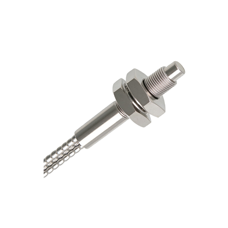
Primary Causes of Sensor Disconnection
Several factors can lead to the failure of a photoelectric sensor's connection. Physical damage to the cable is a common culprit, often resulting from constant flexing, abrasion against sharp edges, crushing by moving machinery, or exposure to extreme temperatures that degrade insulation. Loose or corroded electrical connections at the terminal blocks, connectors, or plug interfaces can create intermittent signals or complete loss of connection. Environmental factors play a significant role; excessive moisture, oil, dust, or chemical vapors can infiltrate connectors or damage cable sheathing. Internal sensor failure, though less frequent, can also manifest as a disconnection from the control system. Additionally, electrical noise from nearby high-voltage equipment, variable frequency drives (VFDs), or welding machines can induce interference on the signal lines, effectively disrupting communication and mimicking a physical disconnection.
Systematic Troubleshooting Procedure
A methodical approach is key to efficiently diagnosing and resolving a photoelectric sensor disconnection. First, perform a visual inspection of the entire sensor assembly, including the housing, lens, cable, and connection points. Look for obvious signs of physical damage, corrosion, or loose fittings. Next, verify the power supply to the sensor using a multimeter. Ensure the voltage at the sensor terminals matches the specified requirements (e.g., 10-30V DC). If power is confirmed, check the sensor's output signal. Activate the sensor's sensing field (e.g., by placing an object in front of it) and measure the output voltage or use the sensor's built-in indicator LED. A functioning sensor with a proper load should switch its output state. If the sensor itself operates correctly, the fault lies in the wiring or the controller input. Perform a continuity test on the signal cable from the sensor output terminal to the PLC input module, checking for opens or shorts. Finally, inspect the PLC input card's status indicator and configuration to rule out controller-side issues.
Advanced Diagnostic Techniques
For intermittent disconnections or complex noise-related issues, more advanced techniques are necessary. Using an oscilloscope to monitor the sensor's output signal and power supply lines can reveal noise spikes, voltage sags, or signal instability that a multimeter might miss. Temporarily replacing the suspected sensor and its cable with a known-good unit is a highly effective isolation test. If the problem disappears, the original component is faulty. For systems with network-connected sensors (e.g., IO-Link), diagnostic software can provide detailed status information, error logs, and parameter settings, offering deep insights into the disconnection event. Monitoring the electrical current draw of the sensor can also indicate internal problems, such as a short circuit or failing components, before they cause a complete failure.
Preventive Maintenance and Best Practices
Proactive measures drastically reduce the incidence of photoelectric sensor disconnections. Implement a regular inspection schedule as part of preventive maintenance. This includes checking cable strain relief, cleaning lenses to prevent false triggers from dirt, and tightening all electrical connections. Proper installation is critical: route cables away from heat sources and moving parts, use conduits or cable carriers in high-flex areas, and ensure adequate bend radius. Select sensors with appropriate ingress protection (IP) ratings (e.g., IP67, IP69K) for the environment—whether it's washdown, dusty, or oily. Employ shielded cables and ensure proper grounding to mitigate electromagnetic interference (EMI). For critical applications, consider using sensors with diagnostic capabilities or redundant sensing setups to provide early warnings of degradation before a complete disconnection occurs.
Conclusion and Key Takeaways
Photoelectric sensor disconnection is a manageable challenge with a clear understanding of its causes and solutions. A disciplined, step-by-step troubleshooting process—from visual checks to signal analysis—enables rapid restoration of operations. However, the most cost-effective strategy is a robust preventive maintenance program focused on correct installation, environmental protection, and regular inspection. By treating sensor connections as vital system components, engineers and maintenance personnel can ensure uninterrupted data flow, maximize equipment uptime, and support the seamless automation that modern industry relies upon. Investing time in proper setup and care pays significant dividends in long-term system reliability.