Understanding Proximity Sensor Fundamentals
Proximity sensors are indispensable components in modern industrial automation, detecting the presence or absence of an object without physical contact. Primarily, they are categorized into inductive, capacitive, and photoelectric types, each with distinct operating principles and applications. Inductive sensors detect metallic objects, capacitive sensors can detect both metallic and non-metallic materials, and photoelectric sensors use light beams. Before commencing any wiring procedure, it is paramount to consult the specific sensor's datasheet. This document provides critical information such as the sensor type (PNP or NNP sourcing/sinking), operating voltage range (commonly 10-30V DC or 90-250V AC), output configuration (normally open NO or normally closed NC), and current rating. A thorough understanding of these specifications is the foundation for a safe and correct installation.
Essential Tools and Safety Precautions
Gather all necessary tools and personal protective equipment before starting. You will typically need a screwdriver set, wire strippers, crimping tools, appropriate gauge wires, and a multimeter for verification. The foremost step is to ensure the complete isolation of the electrical circuit. Lock out and tag out (LOTO) the power source to prevent accidental energization. Verify the absence of voltage using a properly rated voltage tester. Always adhere to local and national electrical codes, such as the NEC (National Electrical Code) or IEC (International Electrotechnical Commission) standards. Wear insulated gloves and safety glasses. Planning the cable routing away from high-voltage lines and sources of electromagnetic interference is also crucial for reliable sensor operation and longevity.
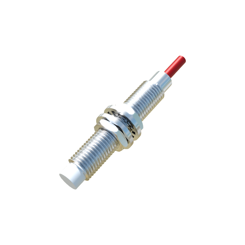
Wiring a 3-Wire DC Proximity Sensor
The 3-wire DC sensor is the most common configuration in industrial control panels. It comprises three distinct wires: brown (or red) for the positive supply voltage (+V), blue for the common negative or 0V, and black (or white) for the output signal. For a PNP (sourcing) sensor, the wiring sequence is as follows: Connect the brown wire to the positive terminal of your DC power supply (e.g., +24V). Connect the blue wire to the negative terminal (0V) of the same power supply. The black output wire is then connected to the load (e.g., a PLC input module, relay coil). The other side of this load must be connected back to the 0V (negative) of the power supply. When the sensor detects a target, it will "source" current from the +V, through the sensor's output transistor, out the black wire, through the load, and back to 0V, completing the circuit.
Wiring a 2-Wire DC Proximity Sensor
Two-wire sensors are simpler in design, acting like a switch in series with the power supply and the load. They have only two connection wires, typically brown and blue. There is no dedicated output wire; the sensor modulates the current flow through itself. The wiring procedure involves connecting one wire (brown) to the positive side of the power supply. The other wire (blue) is connected to one terminal of the load. The remaining terminal of the load is then connected to the negative side of the power supply, forming a complete series loop. It is critical to note that these sensors have a residual voltage drop (leakage current) even in the "off" state. This leakage must be considered when connecting to highly sensitive PLC inputs, as it might be misinterpreted as an "on" signal. A bypass resistor may be required per the PLC manufacturer's guidelines.
Connecting to a PLC Input Module
Integrating a proximity sensor with a Programmable Logic Controller (PLC) is a standard practice. The connection method depends on the PLC input type (sinking or sourcing) and the sensor type. For a system using a PNP sensor and a sinking PLC input module: Wire the sensor's brown (+V) and blue (0V) to the DC power supply. Connect the sensor's black output wire directly to the designated PLC input terminal. The PLC input module's common point for that group of inputs must be connected to the 0V of the power supply. When activated, the PNP sensor sources current into the PLC input. Conversely, for an NPN sensor with a sourcing PLC input, the sensor's output wire connects to the input, and the PLC common is connected to +V. Always ensure the voltage and current ratings of the sensor output are compatible with the PLC input specifications to avoid damage.
Testing and Troubleshooting Common Issues
After wiring, a systematic testing phase is essential. First, restore