Fundamental Operating Principle
Inductive proximity sensors are non-contact electronic devices designed to detect the presence or absence of metallic objects without physical contact. At their core, they operate on the principle of electromagnetic induction. The sensor generates a high-frequency oscillating electromagnetic field from its active face, which is produced by a coil wound around a ferrite core. When a conductive metal target enters this field, eddy currents are induced on the surface of the target. These eddy currents draw energy from the oscillator circuit within the sensor, causing a measurable change in the oscillation amplitude. An internal evaluation circuit detects this amplitude reduction and triggers a switching signal, typically changing the state of the sensor's output from high to low or vice versa. This robust principle allows for reliable detection of ferrous metals like steel and iron, as well as non-ferrous metals such as aluminum, copper, and brass, though with varying sensing distances.
Key Technical Characteristics and Specifications
Understanding the specifications is crucial for proper sensor selection. The nominal sensing distance (Sn) is a fundamental parameter, indicating the standard detection range under defined conditions. It is important to note that the effective sensing distance can be reduced when detecting non-ferrous metals. The repeat accuracy defines the sensor's precision in consistently detecting a target at the same point. Hysteresis is another critical feature, a built-in differential between the switch-on and switch-off points that prevents output chattering when a target is at the exact sensing limit. Operating frequency specifies how many switching cycles per second the sensor can handle, a vital factor in high-speed automation. Furthermore, environmental ratings like IP67 or IP69K for ingress protection against dust and water, and temperature ranges, ensure reliable operation in harsh industrial settings. The output configuration, whether NPN (sinking) or PNP (sourcing), and the connection type (2-wire, 3-wire, or 4-wire) must be compatible with the control system's PLC or input card.
Common Industrial Applications and Use Cases
The robustness and reliability of inductive sensors make them ubiquitous in factory automation. A primary application is position sensing, such as verifying the presence of a metal part on a conveyor, confirming the end position of a cylinder, or detecting the passage of gear teeth for speed monitoring. They are indispensable in machine tools for tool breakage detection and workpiece positioning. In material handling, they count metal parts, control sorting gates, and provide end-of-travel limits for actuators. Their sealed metal housings allow them to perform reliably in dirty environments—like stamping, welding, and machining—where optical sensors might fail due to coolant, oil, or metal shavings. Specialized variants, like factor-1 cylindrical sensors immune to interference from adjacent metals, or weld-field immune models that ignore strong magnetic fields from welding equipment, solve specific application challenges.
Advantages Over Other Sensor Technologies
Inductive proximity sensors offer distinct benefits that justify their widespread use. Their primary advantage is extreme durability; with no moving parts and sealed housings, they resist mechanical wear, vibration, and harsh contaminants. They provide consistent performance unaffected by ambient light conditions, opaque fluids, or surface color, unlike photoelectric sensors. Their output switching is fast and bounce-free, suitable for high-speed counting. Compared to capacitive sensors, they are unaffected by non-metallic materials like wood, plastic, or liquids, leading to fewer false triggers in environments with varying humidity or material types. This target specificity for metals simplifies setup and increases application reliability. Their simple, solid-state design generally translates to long service life and minimal maintenance requirements.
Critical Selection Criteria and Installation Tips
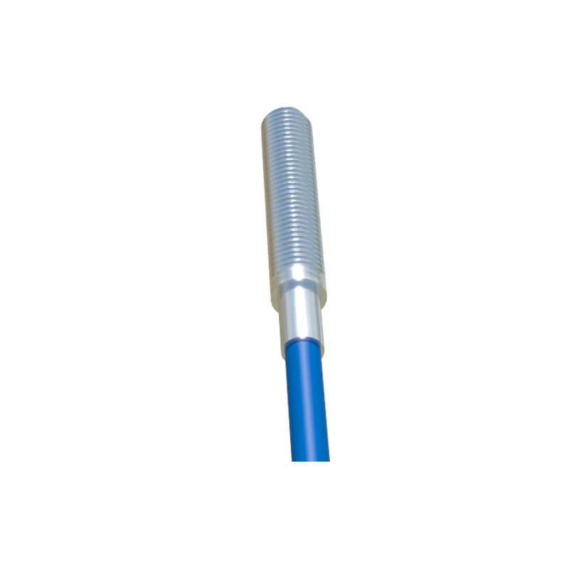
Selecting the correct sensor involves several considerations. First, identify the target material and required sensing distance, accounting for any reduction factors for non-ferrous metals. The sensor housing shape and size must fit the mechanical constraints; cylindrical (threaded barrel) and rectangular block styles are most common. Choose the appropriate electrical output type (NPN/PNP) and voltage range (e.g., 10-30V DC) to match the control system. For installation, ensure the sensor is mounted securely to prevent misalignment. Maintain the recommended lateral and face-to-face spacing between multiple sensors to prevent mutual interference. Always consider the environment: high-temperature applications require sensors with extended thermal ratings, while wash-down areas need high IP ratings. Finally, ensure the sensing face is flush-mounted or recessed if specified, as the sensing field extends from the front surface, and surrounding metal (except for factor-1 types) can diminish the effective range.