Introduction to Photoelectric Sensors
Photoelectric sensors are widely used in industrial automation for detecting objects, measuring distances, and ensuring safety. These sensors operate by emitting a light beam—typically infrared, visible, or laser—and detecting changes in the received light due to the presence or absence of an object. The core components include a light emitter, a receiver, and signal processing circuitry. Understanding their working principles is essential for designing effective connection circuits, as it influences the choice of wiring, power supply, and output configuration. Proper integration ensures reliable performance in diverse environments, from manufacturing lines to robotic systems.
Types of Photoelectric Sensors
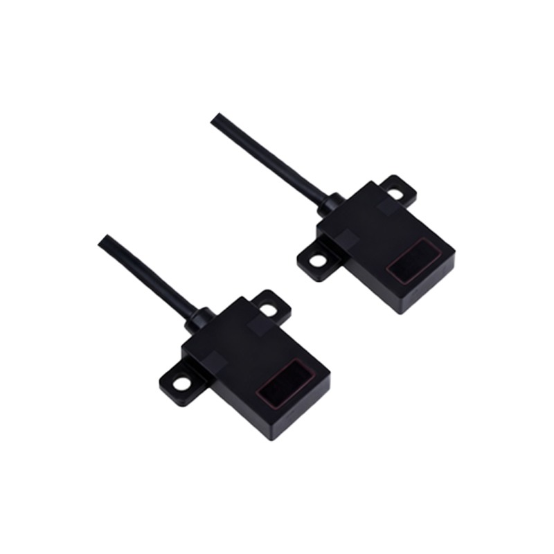
Photoelectric sensors are categorized based on their detection methods: through-beam, retro-reflective, and diffuse-reflective. Through-beam sensors consist of separate emitter and receiver units, offering long-range and high-accuracy detection. Retro-reflective sensors use a reflector to bounce light back to the receiver, making them suitable for medium-range applications. Diffuse-reflective sensors rely on light reflected directly from the object, ideal for short-range tasks. Each type requires specific connection circuits to handle signal output, such as NPN or PNP transistors, analog voltage, or relay-based interfaces. Selecting the right sensor type depends on factors like detection distance, object material, and environmental conditions.
Basic Connection Circuit Components
A standard photoelectric sensor connection circuit includes a power supply, sensor unit, load device, and protective elements. The power supply typically provides 12-24 VDC, ensuring stable operation. The sensor unit integrates the emitter and receiver, with internal circuitry converting light signals into electrical outputs. Load devices, such as PLCs, relays, or indicators, are connected to the sensor's output terminals. Protective elements like fuses, surge protectors, and shielding cables prevent damage from voltage spikes or electrical noise. Proper grounding and isolation are critical to minimize interference, especially in high-noise industrial settings.
Wiring Configurations for NPN and PNP Outputs
Photoelectric sensors commonly feature NPN (sinking) or PNP (sourcing) transistor outputs. NPN outputs connect the load to the positive voltage supply, with the sensor switching the ground path—suitable for PLCs with sinking input modules. PNP outputs connect the load to ground, with the sensor switching the positive path—compatible with sourcing input modules. Wiring diagrams must be followed precisely: for NPN, the load is placed between the output and positive supply; for PNP, between the output and ground. Incorrect wiring can lead to malfunction or damage. Always refer to the sensor datasheet for voltage and current ratings to ensure compatibility with the load.
Analog and Digital Output Circuits
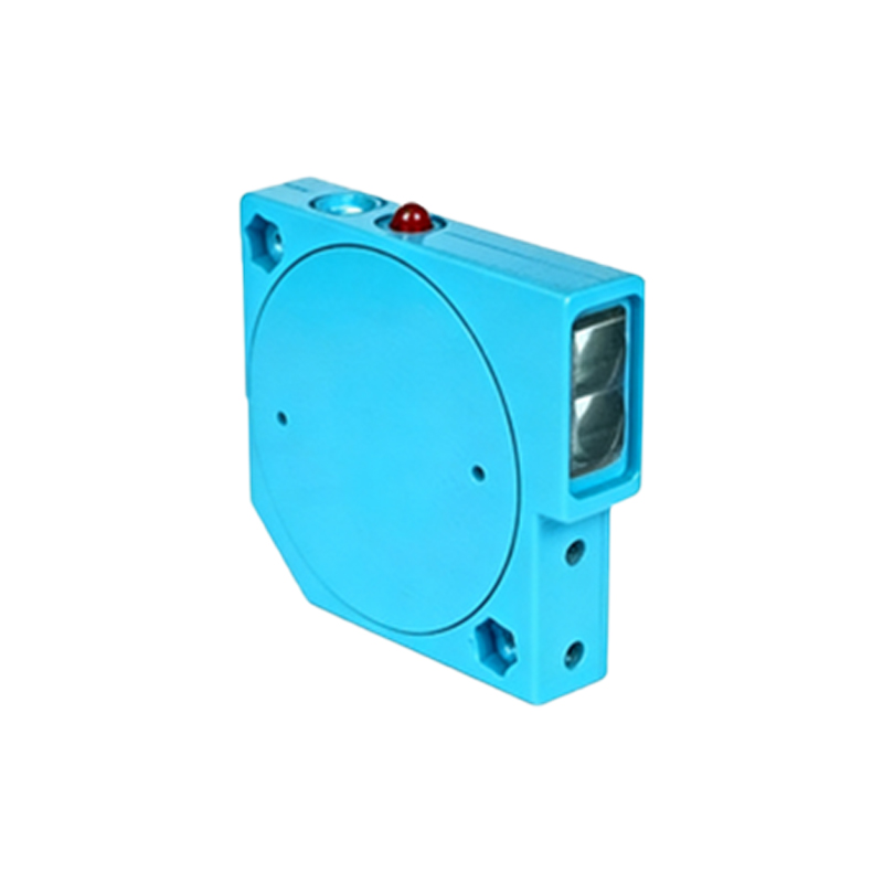
Beyond discrete outputs, photoelectric sensors may offer analog or digital interfaces. Analog outputs, such as 0-10 V or 4-20 mA signals, provide continuous data for distance or intensity measurement, requiring connection to analog input modules on controllers. Digital outputs, including push-pull or open-collector circuits, deliver on/off signals for simple detection tasks. For analog circuits, use shielded twisted-pair cables to reduce noise, and calibrate the sensor to match the controller's range. Digital circuits benefit from pull-up or pull-down resistors to stabilize signals. Implementing these circuits correctly enhances precision in applications like level sensing or color recognition.
Integration with Programmable Logic Controllers (PLCs)
Connecting photoelectric sensors to PLCs involves matching the sensor output to the PLC input module. For DC sensors, ensure the voltage levels align—e.g., 24 VDC sensors with 24 VDC input modules. Use interposing relays if voltage mismatches occur. Wiring typically involves connecting the sensor output to the PLC input terminal, with common terminals linked to the power supply. Ladder logic programming then processes the input signals for control actions, such as activating motors or alarms. Test the connection with a multimeter to verify signal integrity, and employ diagnostic tools in the PLC software for troubleshooting.
Noise Reduction and Shielding Techniques
Industrial environments often contain electromagnetic interference (EMI) that can disrupt sensor signals. To mitigate noise, use shielded cables with the shield grounded at one end—preferably at the controller side. Keep sensor cables away from power lines and motors. Incorporate ferrite beads or filters near the sensor or PLC to suppress high-frequency noise. For sensitive analog circuits, consider differential signaling or isolation amplifiers. Regular maintenance, such as checking cable integrity and cleaning sensor lenses, also reduces false triggers. These practices ensure stable operation in facilities with heavy machinery or variable loads.
Safety Considerations and Compliance
Safety is paramount when designing photoelectric sensor circuits. Follow standards like IEC 60947 for electrical safety and ISO 13849 for machine safety. Use redundant circuits or fail-safe sensors in critical applications, such as emergency stops or guard monitoring. Ensure proper insulation and overcurrent protection to prevent short circuits. Label all connections clearly and document the wiring layout for future reference. Training personnel on safe installation and troubleshooting procedures minimizes risks. Compliance with regional regulations, such as CE or UL markings, guarantees that the system meets industry benchmarks for reliability and safety.
Troubleshooting Common Connection Issues
Common issues in photoelectric sensor circuits include no output signal, intermittent operation, or false detections. Start by checking the power supply voltage and polarity with a multimeter. Inspect wiring for loose connections or damage. Verify that the sensor alignment and lens are clean and unobstructed. For noise-related problems, reassess shielding and grounding. Consult the sensor manual for diagnostic LEDs or output indicators. If using a PLC, monitor input statuses to identify signal drops. Replace faulty components, such as damaged cables or sensors, and retest the circuit under operational conditions. Keeping spare parts on hand reduces downtime.
Advanced Applications and Future Trends
Photoelectric sensors are evolving with advancements in connectivity and smart technology. Industrial IoT integration allows sensors to transmit data via Ethernet/IP or IO-Link for real-time monitoring and predictive maintenance. Fiber-optic sensors enable detection in extreme temperatures or hazardous areas. Future trends include miniaturization, enhanced precision with AI-based signal processing, and wireless connectivity for flexible installations. Designing connection circuits for these innovations requires adapting to higher data rates and network protocols. Staying updated with industry developments ensures that engineers can implement cutting-edge solutions for automation challenges.