Introduction to Proximity Sensor Switches
Proximity sensor switches are fundamental components in modern industrial automation, providing non-contact detection of metallic and non-metallic objects. These devices operate by emitting an electromagnetic field or a beam of electromagnetic radiation and detecting changes in the field or return signal. The primary advantage lies in their ability to function without physical contact, thereby eliminating mechanical wear and tear, increasing operational lifespan, and ensuring high reliability in harsh environments. Common types include inductive, capacitive, ultrasonic, and photoelectric sensors, each suited for specific applications based on target material, sensing distance, and environmental conditions. Their integration into control systems allows for precise monitoring, counting, positioning, and safety interlocking, forming the backbone of efficient manufacturing and material handling processes.
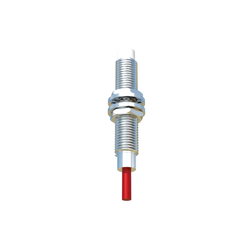
Case Study: Automotive Assembly Line
A prominent automotive manufacturer faced recurring downtime and quality issues on a critical assembly line responsible for installing engine blocks. The existing mechanical limit switches used for verifying the presence and correct positioning of the block were failing frequently due to exposure to oil, metal shavings, and constant physical impact. This led to misaligned installations, production halts, and costly rework. The engineering team proposed replacing all mechanical switches with rugged, IP67-rated inductive proximity sensors. These sensors were selected for their ability to detect the ferrous metal of the engine block reliably from a set distance. The implementation involved precise mounting to detect the block at three key verification points before allowing the robotic arm to proceed. The result was a dramatic 95% reduction in sensor-related failures, a 15% increase in line speed due to the elimination of mechanical delay, and a significant improvement in installation accuracy, virtually eliminating rework.
Technical Specifications and Selection Criteria
Selecting the correct proximity switch requires a detailed analysis of application parameters. Key specifications include sensing distance, which must account for installation tolerances and target size. For inductive sensors, the target material (steel, aluminum, brass) affects the effective sensing range, often requiring derating for non-ferrous metals. The housing material, such as nickel-plated brass or stainless steel, must withstand the operational environment—resisting chemicals, temperature extremes, and physical abrasion. Output configuration is critical; NPN (sinking) or PNP (sourcing) transistor outputs must match the PLC input card. Other vital criteria include response frequency for high-speed applications, shielding type (shielded sensors allow flush mounting in metal, while unshielded offer longer ranges), and connection method (pre-wired cables or quick-disconnect). A thorough review of these factors ensures optimal performance and system integration.
Installation and Calibration Best Practices
Proper installation is paramount for reliable sensor operation. Mounting must be secure to prevent vibration-induced misalignment. A minimum clearance between sensors and between the sensor and surrounding metal (as specified by the manufacturer) must be maintained to prevent mutual interference. For inductive sensors, the sensing face should be parallel to the target surface for maximum range and repeatability. Calibration often involves adjusting the sensor's position or sensitivity potentiometer to achieve a stable detection signal with an adequate margin, typically 20-30% below the rated sensing distance, to compensate for temperature drift and power supply fluctuations. Environmental protection, such as using protective boots in weld spatter zones, extends sensor life. Regular maintenance checks should verify mounting integrity, cleanliness of the sensing face, and signal stability.
Troubleshooting Common Operational Issues
Even with proper selection and installation, issues can arise. Common problems include failure to detect the target, intermittent operation, or shortened sensing range. A systematic approach begins with verifying power supply voltage and polarity. Next, inspect the sensing face for contamination like dirt, grease, or paint buildup. Check for physical damage to the housing or cable. Using a multimeter, measure the output signal status with and without a target present to confirm switching function. Electrical noise from nearby motors or variable frequency drives can cause erratic behavior; solutions include using shielded cables, proper grounding, installing ferrite cores, or relocating the sensor. If the sensing range has degraded, it may indicate a failing oscillator circuit within the sensor, necessitating replacement.
Integration with PLC and Control Systems
The true value of a proximity sensor is realized through seamless integration into the broader control system. The sensor's discrete digital signal (ON/OFF) is typically wired to a programmable logic controller input module. Programming within the PLC ladder logic uses this input to trigger actions—starting a timer, incrementing a counter, enabling a motor, or setting a flag for machine status. Advanced diagnostics can be programmed by monitoring the sensor's state during specific machine cycles; an unexpected state can trigger an alarm or a safe shutdown. In networked systems, IO