Introduction to Photoelectric Sensors in Industrial Automation
Photoelectric sensors are fundamental components in industrial automation, widely used for detecting the presence, absence, or position of objects without physical contact. These sensors operate by emitting a light beam—typically infrared, visible, or laser—and measuring the reflection or interruption of that beam. In programmable logic controller (PLC) systems, photoelectric sensors serve as critical input devices, providing real-time data to control machinery, conveyor systems, and safety mechanisms. Their non-contact nature makes them ideal for harsh environments where durability and reliability are paramount. Understanding how to represent these sensors in PLC programming is essential for engineers to design efficient and responsive automation solutions.
Types of Photoelectric Sensors and Their Operational Principles
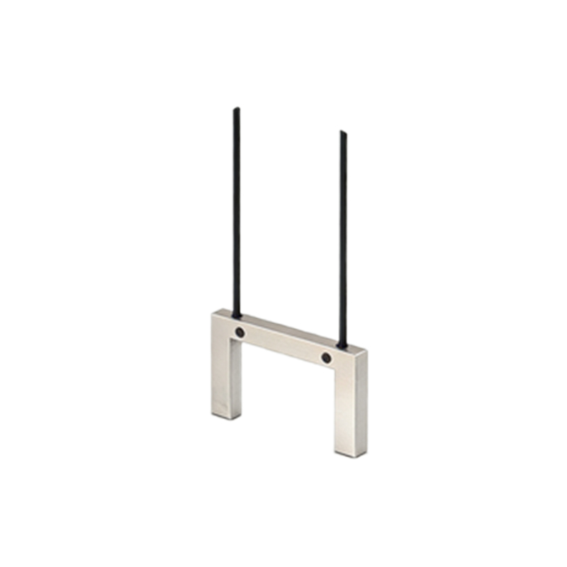
Photoelectric sensors are categorized into three main types based on their sensing methods: through-beam, retro-reflective, and diffuse reflective. Through-beam sensors consist of separate emitter and receiver units; an object is detected when it interrupts the light beam between them. Retro-reflective sensors use a single unit that emits light toward a reflector, with detection occurring when the reflected beam is blocked. Diffuse reflective sensors rely on light bouncing off the target object itself. In PLC contexts, each type translates into specific input conditions. For instance, a through-beam sensor might be wired to a discrete input module, where a broken beam signals a logic high (1) to the PLC, indicating an object's presence. Engineers must select the appropriate sensor type based on factors like detection range, environmental conditions, and application requirements to ensure accurate PLC integration.
Wiring and Hardware Configuration for PLC Integration
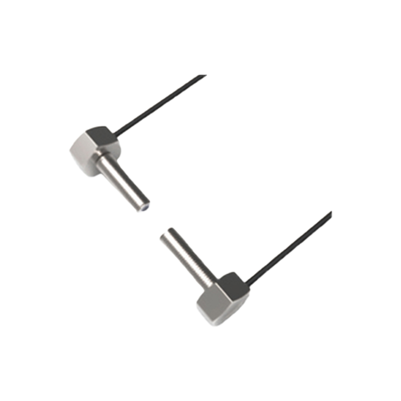
Integrating photoelectric sensors with PLCs involves careful hardware setup. Most photoelectric sensors output discrete signals, either as NPN (sinking) or PNP (sourcing) configurations, which connect to PLC input modules. For example, a common 24V DC sensor might have three wires: brown for positive voltage, blue for ground, and black for the signal output. When the sensor detects an object, the black wire switches to either 0V (NPN) or 24V (PNP), sending a signal to the PLC input point. In ladder logic programming, this input is typically represented as a contact (e.g., I0.0 for input 0 on rack 0). Engineers must ensure compatibility between sensor output types and PLC input specifications to avoid malfunctions. Additionally, shielding and proper grounding are crucial to prevent electrical noise interference, which can cause false triggers in PLC logic.
Representing Photoelectric Sensors in PLC Ladder Logic
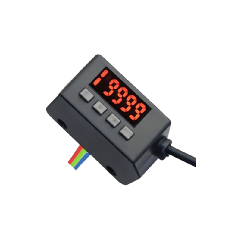
In PLC programming, photoelectric sensors are represented as input contacts within ladder logic diagrams. For a basic detection application, a sensor input (e.g., assigned to address I:1/0) is used as a normally open (NO) or normally closed (NC) contact. When the sensor detects an object, the contact state changes—activating rungs to control outputs like motors or valves. Consider a conveyor system: a photoelectric sensor at the start point might be programmed as an NO contact in a rung that energizes a motor coil (O:2/1). When an object breaks the beam, I:1/0 closes, allowing current flow to O:2/1 and starting the conveyor. Advanced logic can incorporate timers or counters for object tracking. For instance, a sensor triggering a counter instruction can monitor production quantities, with the PLC updating human-machine interface (HMI) displays in real-time.
Addressing and Tagging for Enhanced PLC Programming
Modern PLC systems, such as Siemens SIMATIC or Allen-Bradley ControlLogix, use symbolic addressing or tagging to represent photoelectric sensors intuitively. Instead of raw addresses like I0.0, programmers assign descriptive tags (e.g., "PhotoSensor_Entry") in software like TIA Portal or Studio 5000. This practice improves code readability and maintenance. For example, a tag named "PartDetected" linked to a sensor input can be used in function block diagrams or structured text for complex logic. Additionally, sensors in networked systems, like those connected via PROFINET or EtherNet/IP, are configured with IP addresses and device names in the PLC's I/O tree. Engineers must map these tags correctly in the PLC program to ensure seamless communication between sensors, PLCs, and other automation components, facilitating troubleshooting and scalability.
Error Handling and Diagnostics in PLC Applications
Reliable representation of photoelectric sensors in PLCs includes implementing error-handling routines. Sensors can fail due to misalignment, contamination, or wiring issues, leading to false readings. In ladder logic, engineers add diagnostic bits or alarm routines to monitor sensor health. For instance, a timer instruction can check if a sensor input remains active too long, triggering an alarm output (e.g., "Sensor_Fault") on an HMI. Some PLCs support built-in diagnostics via special function blocks that read sensor status codes over industrial networks. Regular calibration and simulation tools in PLC software, like forcing inputs on/off, help test sensor logic without physical hardware. By incorporating these practices, engineers ensure robust systems that minimize downtime and enhance safety in automated processes.
Best Practices for Optimization and Future Trends
To optimize photoelectric sensor representation in PLCs, engineers should follow industry best practices. This includes using modular programming techniques, such as creating reusable function blocks for common sensor tasks, and documenting logic thoroughly with comments. As Industry 4.0 advances, smart sensors with integrated IO-Link or Ethernet capabilities are becoming prevalent, allowing direct data exchange (e.g., detection counts or health metrics) with PLCs without additional wiring. PLC programs can leverage this data for predictive maintenance and analytics. Staying updated with standards like IEC 61131-3 for PLC programming languages ensures compatibility and efficiency. Ultimately, mastering the representation of photoelectric sensors in PLCs empowers engineers to build flexible, high-performance automation systems that adapt to evolving industrial demands.