Introduction to 3-Wire Proximity Sensors
In the realm of industrial automation, proximity switches stand as fundamental components for non-contact object detection. Among the various configurations, the 3-wire proximity sensor is arguably the most prevalent and versatile type deployed across countless applications. Unlike their 2-wire counterparts, 3-wire sensors provide a dedicated power supply, ground, and output signal wire. This distinct wiring architecture offers superior performance, including faster switching speeds, more stable operation, and the ability to handle higher loads directly. Typically operating on DC voltage (commonly 10-30V DC), these sensors output a switched signal—either normally open (NO) or normally closed (NC)—to a controller like a PLC, signaling the presence or absence of a target within their sensing range. Their robustness, reliability, and precision make them indispensable in manufacturing, packaging, material handling, and automotive assembly lines.
Internal Circuitry and Operating Principle
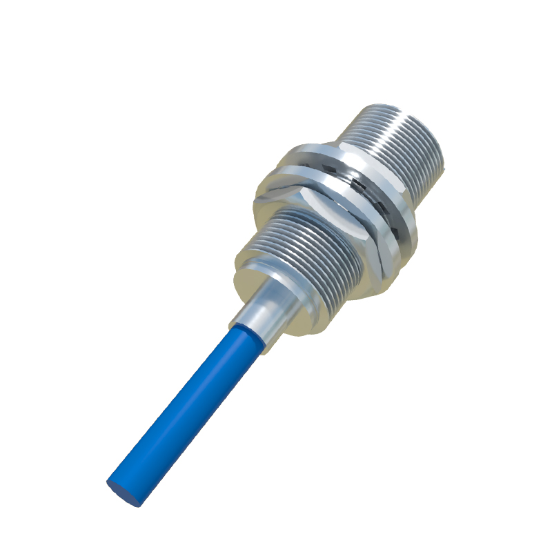
The core of a 3-wire inductive proximity switch (the most common type for metal detection) is an oscillator circuit that generates a high-frequency electromagnetic field at its active face. When a metallic target enters this field, eddy currents are induced in the target, causing a dampening or loading of the oscillator's amplitude. This change is detected by a threshold circuit, which subsequently triggers a solid-state switch (like a transistor) on the output line. For capacitive types, the principle involves changes in capacitance. The three wires are distinctly colored for universal identification: brown for positive DC supply (+V), blue for common negative or ground (0V), and black for the switched output signal. The output transistor can be configured as PNP (sourcing) or NPN (sinking), a critical distinction that determines the current flow path and compatibility with control systems.
Wiring Configurations: PNP vs. NNP
Correctly identifying and wiring the output type is paramount for system functionality. A PNP (Positive-Negative-Positive) sensor, also known as a sourcing sensor, switches the positive voltage to the output line. In this configuration, the load (e.g., a PLC input) is connected between the black output wire and the blue negative wire. When activated, the PNP transistor connects the load to positive voltage, sourcing current to it. Conversely, an NPN (Negative-Positive-Negative) sensor, or sinking sensor, switches the negative or ground path. Here, the load is connected between the brown positive wire and the black output wire. Upon activation, the NPN transistor connects the load to ground, sinking current from it. The choice between PNP and NPN often depends on regional conventions and the specific requirements of the control system's input card.
Key Advantages and Performance Characteristics
The three-wire design confers several significant advantages. Firstly, it allows for low leakage current, ensuring minimal power dissipation when the sensor is off and preventing false triggering in sensitive control circuits. Secondly, it supports higher switching frequencies, often up to several kHz, enabling detection of very fast-moving objects on high-speed production lines. Thirdly, the dedicated output provides a clear, sharp switching signal with excellent repeat accuracy. Key performance specifications include sensing distance (rated and effective), response time, housing material (often nickel-plated brass or stainless steel), IP rating for ingress protection, and temperature range. Their self-contained nature and lack of moving mechanical parts result in exceptional longevity and resistance to vibration, contamination, and wear.
Application Considerations and Installation Best Practices
Successful integration of 3-wire proximity switches requires careful planning. Engineers must select the appropriate sensor type (inductive for metals, capacitive for non-metals, ultrasonic for distance), sensing range, output configuration, and housing shape (barrel, rectangular, ring). Mounting is critical; sensors should be installed securely to avoid vibration, and adequate clearance must be maintained between adjacent sensors to prevent mutual interference. For inductive sensors, the sensing distance can be affected by the target material's properties (steel, aluminum, copper) and size. It is also crucial to ensure proper electrical protection, such as using surge suppressors for long cable runs in electrically noisy environments and verifying voltage polarity to prevent damage. Always refer to the manufacturer's datasheet for specific wiring diagrams and technical limits.
Troubleshooting Common Issues
Even with robust design, issues may arise. Common problems include failure to detect targets, intermittent operation, or sensor damage. A systematic approach to troubleshooting begins with verifying power supply voltage and polarity at the sensor's terminals. Next, check the load and wiring connections for integrity and correct configuration (PNP vs. NPN). Use a multimeter to measure