Introduction to Proximity and Photoelectric Sensor Symbols
In the realm of industrial automation and electrical engineering, schematic diagrams serve as the universal language. Understanding the symbols used for sensors, particularly proximity switches and photoelectric sensors, is fundamental for designing, installing, and troubleshooting control systems. These symbols, standardized by organizations like the International Electrotechnical Commission (IEC) and the National Electrical Manufacturers Association (NEMA), provide a concise graphical representation of a device's function and electrical characteristics. Mastery of these symbols allows engineers and technicians to quickly interpret circuit logic, ensuring efficient system integration and maintenance. This guide delves into the specific symbols for photoelectric sensors, a critical subtype of proximity switches, explaining their variations and applications in detail.
Core Symbol Structure for Photoelectric Sensors
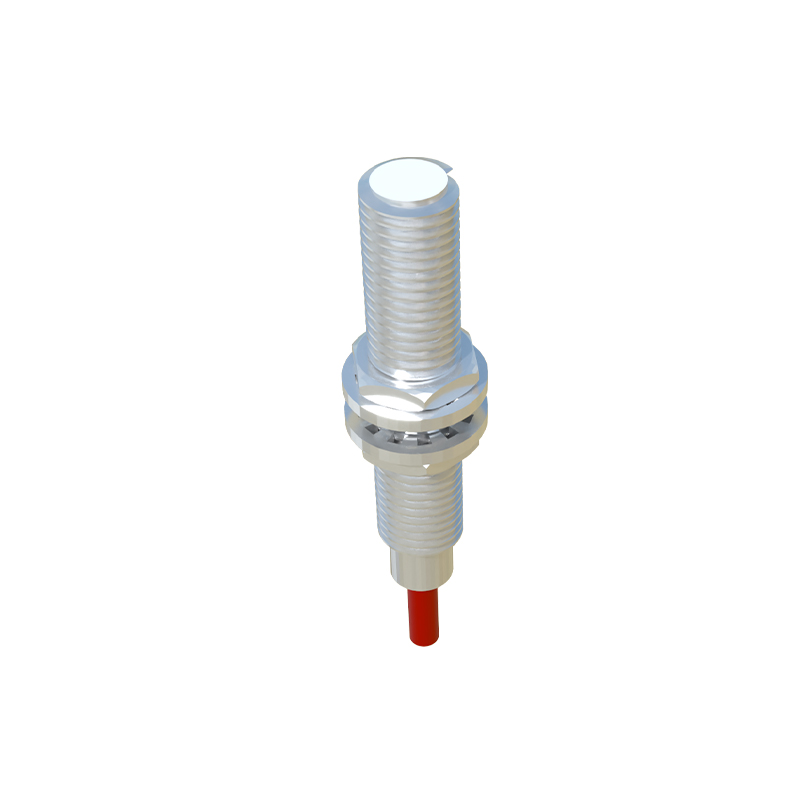
At its heart, the symbol for a photoelectric sensor is built upon the standard symbol for a proximity switch. The base symbol is typically a diamond shape or a rectangle with a diagonal line, representing a switch that is actuated without physical contact. To denote the photoelectric principle, specific graphical elements are added. The most common addition is a pair of parallel rays or arrows emanating from the device, symbolizing the emitted light beam. This distinguishes it from inductive or capacitive proximity sensors. The symbol will also include the standard switch contacts—normally open (NO) or normally closed (NC)—indicating the output state. These contacts are shown in their de-energized or non-actuated position. The housing of the sensor is often represented by a circle or square enclosing the core symbol, with connection points for power supply and output signal clearly marked.
Variations Based on Sensing Modes
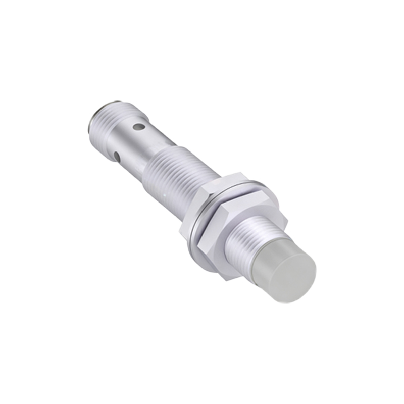
Photoelectric sensors operate in several distinct modes, and their symbols reflect these differences to convey functionality at a glance. For a through-beam sensor, the symbol often shows two separate components: an emitter and a receiver. The emitter symbol features the light rays projecting outward, while the receiver has a similar symbol but may include a small "eye" or a different shading to indicate reception. They are connected by a dashed line representing the light beam. A retro-reflective sensor symbol typically depicts a single unit with the light rays pointing outward and a small graphical element, like a diamond or a corner, representing the reflector. The symbol implies the beam returns to the same device. For diffuse (proximity) sensors, the symbol usually shows the light rays projecting forward and curving back towards the sensor itself, illustrating that the sensor detects light reflected directly from the target object.
Output Configuration and Electrical Details
Beyond the sensing method, the electrical output type is crucial information embedded in the symbol. Symbols will incorporate the standard notations for different output transistors. An NPN (sinking) output is commonly represented by an arrow pointing inward on the output line, indicating that the sensor switches the negative (0V) line. Conversely, a PNP (sourcing) output features an arrow pointing outward, showing the sensor switches the positive voltage line. Some symbols may also include abbreviations like "DC" and the voltage range (e.g., 10-30 VDC). For analog output or specialized types like push-pull (complementary) outputs, additional markings or specific IEC function codes (e.g., a square wave symbol for a digital output) may be integrated near the contact or within the enclosure. This detail is vital for correctly wiring the sensor to a programmable logic controller (PLC) or other control device.
IEC vs. NEMA Symbol Standards
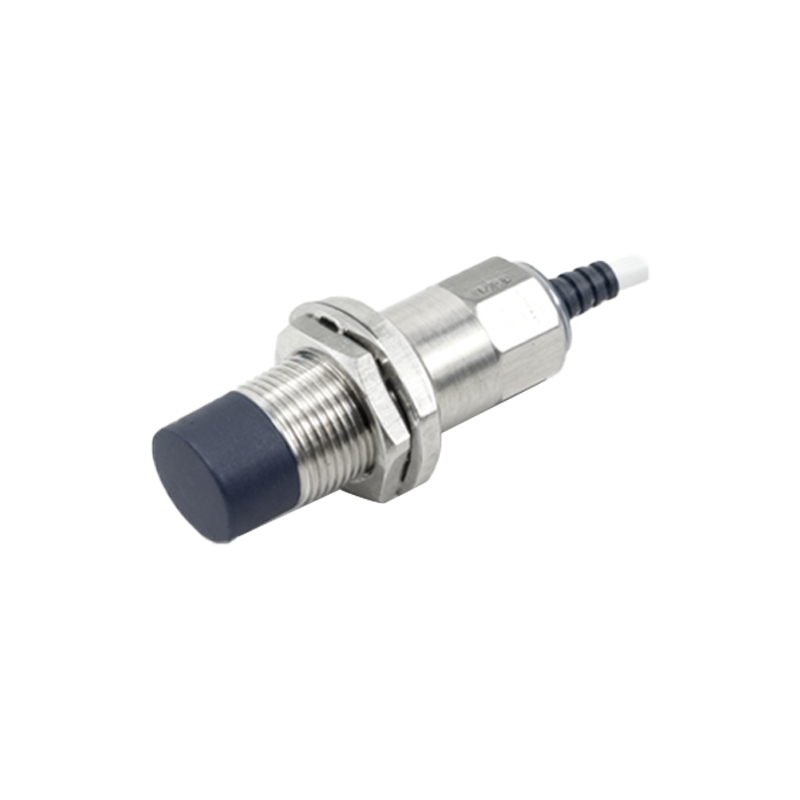
While the underlying principles are similar, slight variations exist between the IEC and older NEMA/JIC symbol standards. IEC symbols, now the global benchmark, tend to be more abstract and functional. The photoelectric element is clearly shown with the light ray symbol, and the enclosure is often a simple circle. NEMA symbols might be slightly more pictorial, sometimes using a more detailed representation of a "light bulb" for the emitter. The switch contact symbols also differ: IEC uses a simple line break for a contact, while NEMA might use a more detailed break symbol. Modern schematic software and international projects predominantly use IEC 60617 standards. Engineers must be familiar with both to interpret legacy diagrams, though new designs should adhere to IEC conventions for clarity and universality.
Practical Application in Circuit Diagrams
In a full ladder logic or power circuit diagram, the photoelectric sensor symbol is not isolated. It is connected to a power supply (L+ and M or 24V and 0V) and its output is wired to an input module of a PLC or directly to a relay coil. The symbol's orientation and the labeling of its terminals (