Introduction to Photoelectric Sensor Wiring
In industrial automation, the correct wiring sequence of photoelectric sensors is paramount for ensuring system reliability and operational safety. These sensors, which detect the presence, absence, or distance of objects using a light transmitter and receiver, are integral to countless applications from packaging lines to robotic assembly. Incorrect wiring can lead to sensor failure, erroneous readings, or even damage to connected machinery. This guide delves into the methodologies and best practices for verifying and maintaining the proper wiring sequence of photoelectric sensors, providing a technical foundation for engineers and technicians.
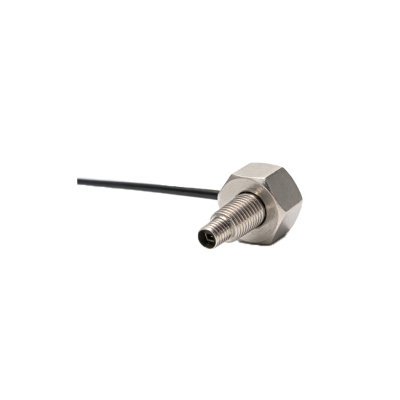
Understanding Sensor Types and Wiring Configurations
Photoelectric sensors primarily come in three types: through-beam, retro-reflective, and diffuse reflective. Each type has distinct wiring requirements. Through-beam sensors consist of separate emitter and receiver units, typically requiring a minimum of three wires: power, ground, and output. Retro-reflective and diffuse models often integrate both emitter and receiver, commonly utilizing a four-wire configuration: brown for positive voltage (V+), blue for common ground (0V), black for normally open (NO) output, and white for normally closed (NC) output. It is crucial to consult the manufacturer's datasheet, as color codes can vary, especially in regional or proprietary designs.
Step-by-Step Procedure for Sequence Verification
A systematic approach is essential for accurate wiring detection. First, ensure all power is disconnected and lockout/tagout procedures are followed. Using a calibrated digital multimeter, begin by checking for continuity between the sensor's housing and the ground wire to verify proper grounding. Next, identify the power wires. With power safely applied, measure the voltage between the suspected V+ and 0V terminals; it should match the sensor's rated voltage (e.g., 10-30V DC). Finally, test the output sequence. Trigger the sensor by interrupting its light beam (using an appropriate target for diffuse types). The multimeter should show a voltage change on the output wire—switching from high to low or low to high depending on the logic (PNP vs. NPN) and configuration (NO vs. NC).
Utilizing Diagnostic Tools and LED Indicators
Modern photoelectric sensors are equipped with built-in diagnostic aids. Most feature a status LED that provides immediate visual feedback. A steady green light often indicates power is correctly applied and the sensor is operational. A flashing light may signify alignment issues, contamination on the lens, or wiring faults in the output circuit. For advanced diagnostics, many sensors support IO-Link communication, allowing for detailed parameter monitoring and sequence validation directly from a PLC or diagnostic software. This digital interface can report real-time data such as signal strength, operating time, and even wire connection integrity, preempting many sequence-related failures.
Common Wiring Errors and Troubleshooting
Several recurrent errors complicate wiring sequence detection. Reversing power polarity is a critical mistake that can instantly damage the sensor's internal circuitry. Incorrectly connecting the output load to the wrong wire (e.g., connecting to an NC terminal when an NO signal is required) will cause the control system to behave inversely. Another frequent issue is electromagnetic interference (EMI) from nearby motors or drives, which can induce noise on signal wires, mimicking a faulty sequence. To troubleshoot, always double-check wire colors against the manual, use shielded cables for signal lines with proper grounding, and employ an oscilloscope to inspect the output signal for clean switching without noise.
Best Practices for Installation and Maintenance
Prevention is superior to correction. During installation, always use the correct gauge of wire and secure connections with ferrules to prevent strand breakage. Clearly label both ends of each wire according to a consistent scheme. Implement a periodic maintenance schedule that includes visual inspection for wire degradation, connector corrosion, and verification of the output signal under operational conditions. For critical applications, consider installing wiring harnesses with sequence-checking connectors or utilizing sensors with pin-assignment monitoring features. Documenting the as-built wiring diagram and any changes made during troubleshooting is invaluable for long-term system upkeep.
Impact of Correct Sequencing on System Performance
Accurate wiring sequence detection directly influences overall system performance. A correctly wired sensor ensures maximum sensing range, optimal response time, and stable operation across temperature fluctuations. It minimizes false triggers that can cause production stoppages and reduces stress on the sensor's electronic components, thereby extending its service life. In safety-critical applications, such as light curtains or interlock systems, verifying the wiring sequence is not merely a technical task but a legal and ethical imperative to protect personnel and equipment.
Conclusion and Future Trends
Mastering photoelectric sensor wiring sequence detection is a fundamental skill in industrial electrical engineering. As sensor technology evolves, trends point toward increased integration of self-diagnostic capabilities and digital twins. Future sensors may automatically report wiring faults and even correct minor sequence errors through intelligent switching circuits. However, the core principles of understanding electrical specifications, methodical testing, and adherence to safety protocols will remain constant. By applying the techniques outlined here, professionals can ensure their automated systems achieve peak reliability and efficiency.