Introduction to Proximity Sensor Types
In the realm of industrial automation, proximity sensors are indispensable components for non-contact object detection. Among the various classifications, the designations C1 and C2 frequently appear in technical datasheets and product catalogs. These codes are not arbitrary; they represent critical electrical output configurations that define the sensor's interface with control systems like PLCs (Programmable Logic Controllers). Understanding the distinction between C1 and C2 is fundamental for selecting the correct sensor for an application, ensuring reliable operation, and preventing potential damage to the sensor or the controller. This article delves into the technical specifics, operational principles, and practical implications of C1 and C2 type proximity sensors.
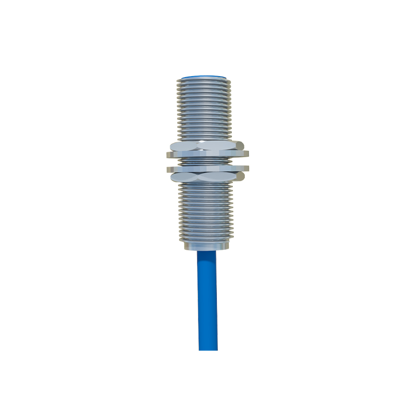
Core Definition: Sourcing vs. Sinking Logic
The fundamental difference between C1 and C2 proximity sensors lies in their output transistor configuration and the resulting current flow. This is often referred to as "sourcing" versus "sinking" logic, a concept central to DC sensor wiring. A C1 type sensor is categorized as a PNP output, or sourcing sensor. In its active state (when it detects a target), it sources positive current from its supply voltage line out through its signal wire to the load. Conversely, a C2 type sensor is an NPN output, or sinking sensor. When active, it provides a path to ground (0V), sinking current from the load through its signal wire. The load, typically the input module of a PLC, must be connected appropriately to complete the circuit.
Detailed Analysis of C1 (PNP) Sensor Operation
A C1 (PNP) proximity sensor has three wires: brown (typically +V DC), blue (typically 0V or common), and a black (output signal). Internally, the output stage uses a PNP transistor. When no target is present, the output transistor is off, and the black signal wire is in a high-impedance state. Upon detection, the PNP transistor switches on, connecting the black wire internally to the positive supply (brown wire). Current now flows from the sensor's output, to the load, and then to the common/ground. For this to work, the load must be connected between the sensor's black wire and the common/ground (blue wire). This configuration is sometimes called "positive logic" in regions like Europe and is standard for many PLC sinking input modules.
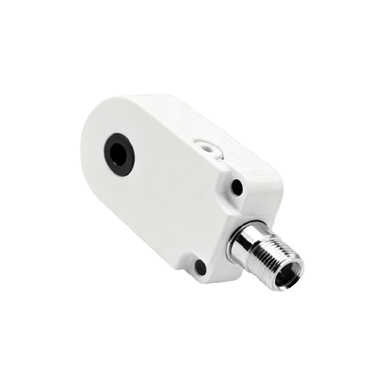
Detailed Analysis of C2 (NPN) Sensor Operation
A C2 (NPN) proximity sensor also has brown (+V), blue (0V), and black (output) wires. Its output stage employs an NPN transistor. In the inactive state, the output is again high-impedance. When activated by a target, the NPN transistor switches on, connecting the black signal wire internally to the common/ground (blue wire). Current flows from the positive supply, through the load, into the sensor's black wire, and is sunk to ground. Here, the load must be connected between the positive supply and the sensor's black wire. This "sinking" or "negative logic" configuration is common in Asia and is used with PLC sourcing input modules.
Wiring Diagrams and Practical Connections
Visualizing the wiring clarifies the distinction. For a C1 (PNP) sensor, the typical connection is: Power supply (+) to brown, Power supply (-) to blue. The load (e.g., PLC input X0) is connected between the black wire and the blue wire (common). When the sensor activates, +V is applied to the PLC input. For a C2 (NPN) sensor, the wiring is: Power supply (+) to brown, Power supply (-) to blue. The load (PLC input X0) is connected between the power supply (+) and the black wire. When active, the black wire connects to ground, completing the circuit through the PLC input. Incorrectly matching a C1 sensor with a sourcing input, or a C2 sensor with a sinking input, will result in no signal transfer.
Key Selection Criteria and Regional Preferences
Choosing between C1 and C2 is primarily dictated by the input circuit of the controller. One must always consult the PLC or controller manual to determine if its digital inputs are configured as "sinking" (requires a positive voltage to activate) or "sourcing" (provides a positive voltage and requires a path to ground). There is no inherent performance advantage; both types are equally reliable. However, regional standards have created preferences: PNP (C1) is often the default in Europe and many