Introduction to Photoelectric Sensor Technology
Photoelectric sensors are pivotal components in modern automation and control systems, utilizing light beams to detect the presence, absence, or distance of objects. These sensors operate by emitting a light source—typically infrared, visible, or laser—toward a target. A receiver then captures the reflected or transmitted light, converting it into an electrical signal. This technology is renowned for its high precision, non-contact operation, and reliability in diverse environments, from clean rooms to harsh industrial settings. In fluid control applications, such as water pumps, photoelectric sensors play a critical role in monitoring liquid levels, flow rates, and system integrity, ensuring efficient and safe operations without physical interference with the medium.
Fundamentals of Water Pump Control Systems
Water pump systems are engineered to move liquids through pipelines or reservoirs, relying on control mechanisms to regulate performance. Traditional pumps often use mechanical switches or float valves for level detection, but these can suffer from wear, corrosion, and inaccuracies. In contrast, integrating photoelectric sensors enhances control by providing real-time, contactless feedback. A typical pump control schematic includes a power supply, motor driver, controller (like a PLC or microcontroller), and sensing units. The photoelectric sensor acts as the eyes of the system, detecting water levels in tanks or flow in pipes, and sending signals to the controller to activate or deactivate the pump motor, thereby preventing overflow, dry running, or inefficiencies.
Schematic Diagram Components and Layout
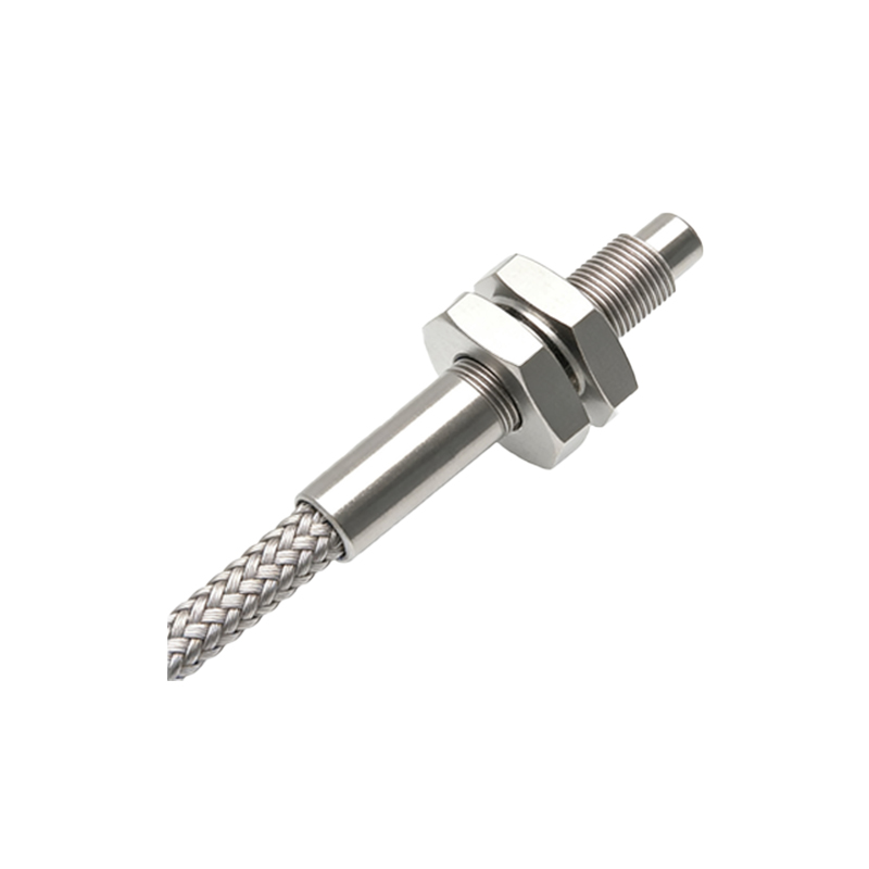
A photoelectric sensor water pump schematic diagram visually represents the electrical and functional connections between components. Key elements include the photoelectric sensor module, which consists of an emitter and receiver pair; the water pump motor, often an AC or DC type; a control unit such as a relay or solid-state switch; and power sources. The diagram typically shows wiring details: the sensor's output wire connects to the control unit's input terminal, while the control unit's output drives the pump motor. Additional components like resistors, capacitors, or diodes may be included for signal conditioning or protection. For instance, in a common setup, the sensor is mounted at a high-level point in a water tank—when water reflects light to the receiver, it triggers the control unit to stop the pump, avoiding overfill.
Working Principle and Signal Flow
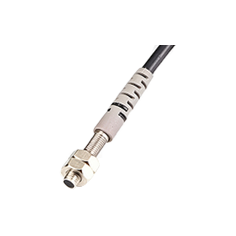
The operational principle revolves around light-based detection and electronic signaling. In a reflective-type photoelectric sensor configuration, the emitter directs a light beam toward the water surface. If water is present, light reflects back to the receiver, which generates a high or low voltage signal. This signal is transmitted to the control unit, interpreted as a "full" condition. The controller then switches off the pump motor via the relay. Conversely, when water drops below the sensor, no reflection occurs, signaling a "low" condition to restart the pump. This closed-loop feedback ensures automated level maintenance. The schematic details this flow: from sensor activation to motor response, highlighting how minimal delay and accuracy are achieved through proper calibration and component selection.
Advantages Over Traditional Sensing Methods
Employing photoelectric sensors in pump schematics offers significant benefits. Firstly, non-contact detection eliminates mechanical wear, reducing maintenance needs and extending system lifespan. Secondly, these sensors provide high sensitivity and fast response times, crucial for preventing water wastage or equipment damage. They are also versatile, functioning in various liquids and temperatures, and resistant to corrosion from chemicals. Compared to float switches or pressure transducers, photoelectric setups allow for more flexible installation and finer control, enabling integration with smart systems for remote monitoring. This makes them ideal for applications in agriculture, HVAC, manufacturing, and domestic water supply, where reliability and efficiency are paramount.
Design Considerations and Best Practices
When designing a photoelectric sensor water pump schematic, engineers must account for several factors. Sensor selection depends on the environment: for clear water, standard infrared sensors suffice, while turbid liquids may require laser types for better penetration. Mounting position is critical to avoid false triggers from splashes or debris. Electrical compatibility—matching voltage levels between sensor, controller, and pump—ensures safe operation. The schematic should include fail-safes, such as backup sensors or alarm circuits, to handle sensor failures. Additionally, using shielded cables minimizes electromagnetic interference, and regular testing of the diagram's logic via simulation software can preempt issues. Adhering to industry standards like IEC or NEC guarantees safety and interoperability.
Common Applications and Real-World Examples
Photoelectric sensor water pump schematics are widely deployed across industries. In residential settings, they automate sump pumps in basements, detecting rising water levels to activate drainage. Industrial uses include cooling systems in machinery, where sensors monitor coolant tanks to maintain optimal levels. Agriculture benefits from automated irrigation pumps that respond to soil moisture indirectly via tank levels. A notable example is in wastewater treatment plants, where sensors control pump stations to manage flow without manual intervention. Each application tailors the schematic—for instance, adding multiple sensors for high and low limits in a tank—showcasing the adaptability of this technology to enhance automation and resource management.
Conclusion and Future Trends
The integration of photoelectric sensors into water pump schematics represents a leap toward smarter, more efficient fluid control systems. By providing precise, contactless detection, these sensors reduce operational costs and improve reliability. As technology advances, trends like IoT connectivity are emerging, allowing sensors to transmit data to cloud platforms for analytics and predictive maintenance. Future schematics may incorporate wireless sensors or AI-driven controllers for adaptive pumping. Engineers and technicians should stay updated on these developments, leveraging photoelectric sensor diagrams to build robust systems that meet evolving demands in sustainability and automation, ultimately driving innovation in water management worldwide.