Understanding Photoelectric Sensors in Punch Press Applications
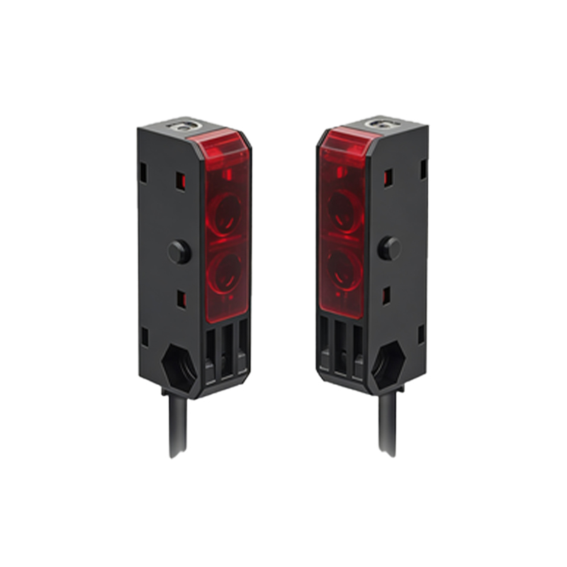
Photoelectric sensors are critical safety and automation components in punch press operations. These devices use light beams to detect the presence or absence of objects, ensuring precise material positioning and preventing accidents by halting machine motion when an obstruction is sensed. In punch press systems, they are often integrated into light curtains or single-point detection setups to safeguard operators and maintain production accuracy. The core principle involves an emitter projecting a light beam to a receiver; any interruption triggers a signal to the control unit. Selecting the right sensor type—such as through-beam, retroreflective, or diffuse—depends on factors like press size, material type, and environmental conditions. Proper installation is essential, as misalignment can lead to false triggers or safety failures, compromising both efficiency and workplace safety.
Components of a Typical Photoelectric Sensor Wiring System
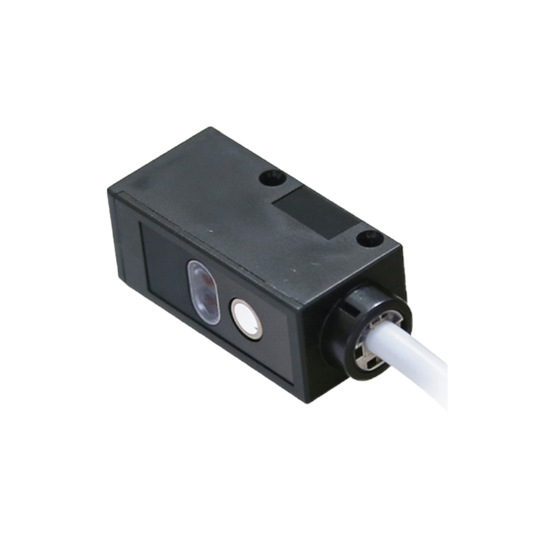
A standard photoelectric sensor wiring setup for a punch press includes several key components. The sensor itself consists of an emitter and receiver, often housed in separate units for through-beam types or combined in one for reflective models. Wiring connects these to a control panel, which typically interfaces with the punch press's programmable logic controller (PLC) or relay system. Power supply lines provide voltage—commonly 12-24V DC or 110-240V AC, depending on the sensor specification—while output signals are transmitted via separate cables. Additional elements may include junction boxes, cable conduits for protection against metal shavings and oil, and indicator lights for status monitoring. Each component must be rated for industrial environments, with high ingress protection (IP) ratings to withstand dust, moisture, and vibrations common in press rooms.
Step-by-Step Wiring Diagram Interpretation
Interpreting a wiring diagram for punch press photoelectric sensors requires attention to symbols and connections. Start by identifying the power source, usually denoted by labels like "V+" and "COM" for DC systems or "L" and "N" for AC. The emitter and receiver are shown with distinct icons, often circles or squares with arrows indicating light direction. Wires are color-coded: typically, brown for positive, blue for negative, and black or white for output signals. In a basic through-beam setup, the emitter's power leads connect to the supply, while the receiver's output links to the PLC input module. Diagrams also include grounding points (marked with earth symbols) to prevent electrical noise interference. Always cross-reference with the sensor datasheet, as pin configurations can vary by manufacturer. For complex systems, such as multi-zone light curtains, diagrams may segment connections by zone, with each sensor chain daisy-chained to a central controller.
Common Wiring Configurations and Best Practices
Wiring configurations for punch press photoelectric sensors depend on the safety and operational requirements. A simple two-wire setup is used for basic detection, where the sensor switches load directly, but it may lack diagnostics. Three-wire systems are more common, offering separate power, ground, and signal lines for reliable performance. For high-risk applications, dual-channel wiring with cross-monitoring is employed, where two independent signals must agree to ensure fail-safe operation. Best practices include using shielded cables to reduce electromagnetic interference from press motors, securing wires away from moving parts to prevent abrasion, and labeling all connections for easy troubleshooting. Regular testing with a multimeter verifies voltage levels and signal integrity. Additionally, adhere to local electrical codes and standards like ISO 13849 for safety systems, ensuring redundancies where needed to mitigate failure risks.
Troubleshooting Wiring Issues and Maintenance Tips
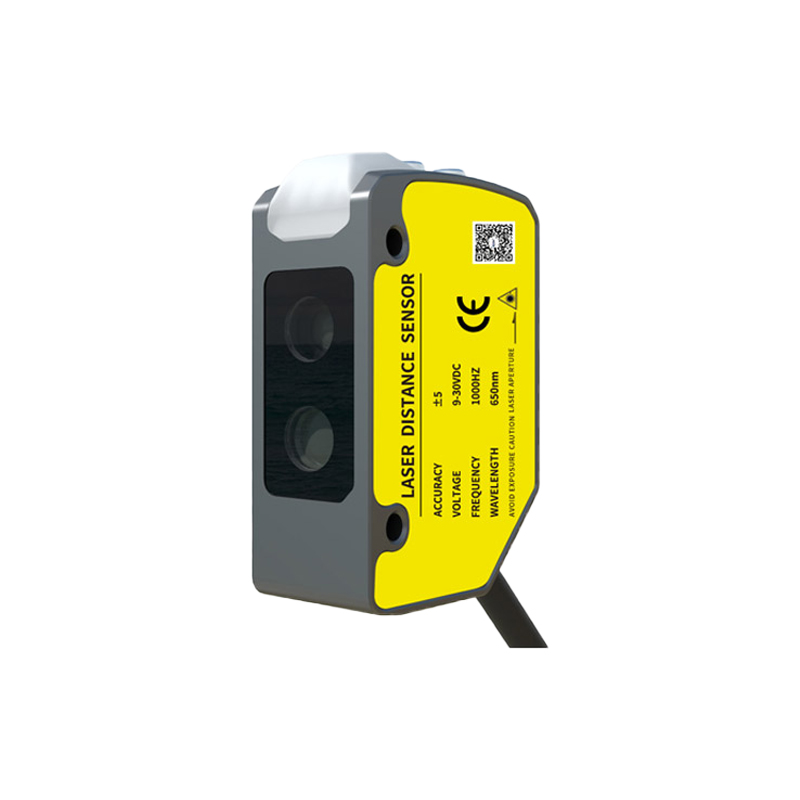
Troubleshooting photoelectric sensor wiring in punch presses involves systematic checks. Begin by inspecting physical connections for looseness or corrosion, especially in humid or oily environments. Use a wiring diagram to trace circuits, testing continuity with a multimeter to identify breaks or shorts. Common issues include misaligned sensors causing intermittent beam breaks, or voltage drops from inadequate power supplies. Indicator lights on sensors help diagnose problems: a steady light often means proper operation, while flashing may indicate alignment or wiring faults. For maintenance, schedule periodic cleaning of sensor lenses to remove dust and debris, and verify wiring integrity during routine press shutdowns. Keep a log of any incidents, as recurring issues might signal the need for component upgrades or layout changes. Always de-energize the press before any wiring work to ensure operator safety.
Enhancing Safety and Efficiency with Proper Wiring
Proper wiring of photoelectric sensors directly enhances both safety and efficiency in punch press operations. A well-wired system minimizes downtime by reducing false stops and equipment damage, while ensuring compliance with safety regulations like OSHA or CE directives. Integrating sensors with the press control allows for automated material handling, speeding up cycles without compromising protection. For future upgrades, consider smart sensors with IO-Link capabilities, which provide detailed diagnostics via digital communication, simplifying wiring through reduced cable counts. Document all wiring changes and train maintenance staff on diagram interpretation to foster a proactive safety culture. Ultimately, investing in correct wiring practices not only protects personnel but also boosts productivity by creating a reliable, responsive punch press environment.