Understanding Photoelectric Sensor Fundamentals
Photoelectric sensors are indispensable components in modern industrial automation, utilizing light beams to detect the presence, absence, or distance of objects. The core principle involves an emitter that projects a light beam—typically infrared, visible red, or laser—and a receiver that detects changes in the received light intensity. When an object interrupts or reflects this beam, the sensor's output state changes, triggering a control action. These sensors are prized for their non-contact operation, long sensing ranges, and high-speed response, making them ideal for applications like object counting, positioning, and level detection in harsh environments. A thorough grasp of their operational theory is the essential first step before any testing or wiring procedure.
Essential Components and Signal Types
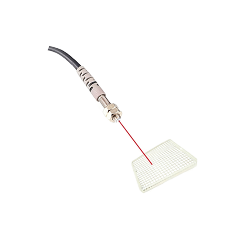
A standard photoelectric sensor system comprises three main parts: the sensor head (containing the emitter and receiver), a cable or connector for power and signal transmission, and a control device like a PLC (Programmable Logic Controller). Sensors are categorized by their optical design: through-beam (separate emitter and receiver), retro-reflective (single unit with a reflector), and diffuse-reflective (single unit detecting reflected light). Regarding electrical output, the two primary types are discrete (digital) and analog. Discrete outputs, either NPN (sinking) or PNP (sourcing), provide a simple ON/OFF signal. Analog outputs, such as 0-10V or 4-20mA, deliver a continuous signal proportional to the detected distance or intensity, used for precise measurement tasks.
Power Supply Requirements and Connections
Correct power supply connection is paramount for safe and reliable sensor operation. Most industrial photoelectric sensors operate on DC voltages, commonly 12-24V DC. The datasheet must always be consulted for the exact voltage range (e.g., 10-30V DC). Wiring involves connecting the positive voltage line (typically brown or red wire) to the sensor's V+ terminal and the negative or 0V line (typically blue or black wire) to the 0V terminal. A stable, regulated power supply is crucial; voltage spikes or noise can cause erratic behavior. For systems with multiple sensors, using a single, adequately rated power supply with proper fusing is standard practice. Always ensure the power is OFF during initial wiring to prevent short circuits or damage.
Output Circuit Wiring Configurations
The output wiring configuration depends entirely on the sensor's transistor type (NPN or PNP) and the input characteristics of the connected load (e.g., PLC input module). An NPN sensor switches the negative (0V) line to the load. In this configuration, the load is connected between the sensor's output wire (typically black) and the positive supply (+V). When activated, the NPN transistor closes the circuit to 0V, allowing current to flow from +V, through the load, and to ground via the sensor. Conversely, a PNP sensor switches the positive voltage line. Here, the load is connected between the output and 0V. Activation connects the load to +V, with current flowing from the sensor, through the load, to ground. Mismatching sensor output type with the load is a common installation error that prevents operation.
Testing Procedures for Verification
After wiring, systematic testing verifies correct installation and functionality. First, perform a visual inspection of all connections for tightness and correct polarity. Apply power and observe the sensor's indicator LED(s). Most sensors have a power (green) and a stability or output (orange/red) LED. The power LED should be steadily lit. Next, test the sensing function. For a through-beam sensor, block the light path between emitter and receiver; the output LED should illuminate, and a multimeter should show a voltage change at the output terminals. For a diffuse sensor, bring a standard test object into the sensing field. Check the response time and sensing range against the datasheet specifications. Finally, integrate the sensor with the control system (PLC) and verify that the correct input is registered in the control software when the sensor is triggered.
Troubleshooting Common Wiring Issues
Even with careful installation, issues can arise. A sensor that fails to power on indicates problems with the supply circuit: check fuse integrity, supply voltage at the sensor terminals with a multimeter, and correct polarity. If the sensor powers on but does not detect objects, verify the optical path is unobstructed and clean the lens. For erratic operation or false triggers, investigate electrical noise. This often requires installing a snubber circuit across the load, using shielded cables grounded at one end only, and ensuring proper separation of sensor cables from high-voltage AC power lines. If the PLC does not recognize the sensor signal, confirm the compatibility between the sensor's output type (NPN/PNP) and the PLC input module's required circuit (sinking or sourcing). Always methodically isolate each system segment—power, sensor, wiring, load—during troubleshooting.
Safety and Best Practices
Adhering to safety and best practices ensures long-term system reliability and personnel safety. Always lock out and tag out (LOTO) power sources before working on electrical connections. Use the correct wire gauge for the current load and secure connections with appropriate terminals or connectors. Implement proper cable management, using conduits or cable carriers in dynamic applications to prevent wire fatigue. For sensors in wash-down or explosive environments, select units with appropriate IP (Ingress Protection) and ATEX/IECEx ratings and ensure cable glands are properly sealed. Regularly schedule maintenance checks to clean optical surfaces and inspect for cable damage. Documenting the wiring diagram and sensor parameters for each machine simplifies future troubleshooting and modification.