Understanding Proximity Sensor Calibration
Proximity sensor calibration is a critical procedure to ensure accurate and reliable detection of objects within a specified sensing range. Calibration adjusts the sensor's output to match a known standard or desired performance characteristic, compensating for manufacturing tolerances, environmental factors, and installation variances. The primary goal is to establish a precise relationship between the sensor's output signal (e.g., voltage, current, or digital state) and the actual distance to the target object. Without proper calibration, a sensor may trigger too early, too late, or not at all, leading to machine malfunctions, process errors, or safety hazards. The calibration process varies significantly between different sensor technologies, including inductive, capacitive, ultrasonic, and photoelectric types. Each type responds to different material properties and environmental conditions, necessitating a tailored approach. A fundamental understanding of the sensor's datasheet parameters, such as nominal sensing distance, hysteresis, and repeatability, is essential before initiating any calibration procedure.
Pre-Calibration Preparation and Safety
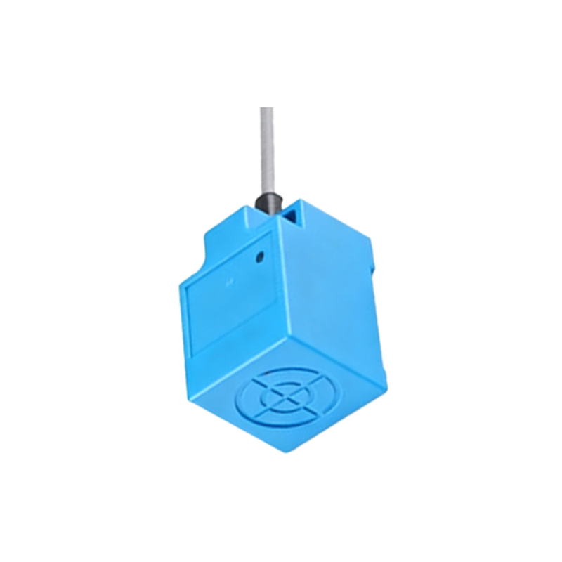
Before beginning the calibration process, thorough preparation is paramount. First, consult the manufacturer's manual for specific instructions, recommended tools, and safety warnings. Ensure the power to the system is locked out and tagged out (LOTO) to prevent accidental energization. Gather the necessary calibration tools, which typically include a set of certified gauge blocks or targets made of the correct material (e.g., mild steel for inductive sensors), a precise measuring device like a digital caliper or micrometer, and a stable mounting fixture. The environment should be stable, with ambient temperature close to the operational temperature to minimize thermal drift effects. Inspect the sensor and its mounting for any physical damage, misalignment, or contamination from oil, dust, or metal chips. Clean the sensing face and the target surface meticulously. Verify the electrical connections and the integrity of the cabling, as poor connections can mimic calibration drift. Document the sensor's initial settings and performance as a baseline for comparison.
Calibration Procedure for Inductive and Capacitive Sensors

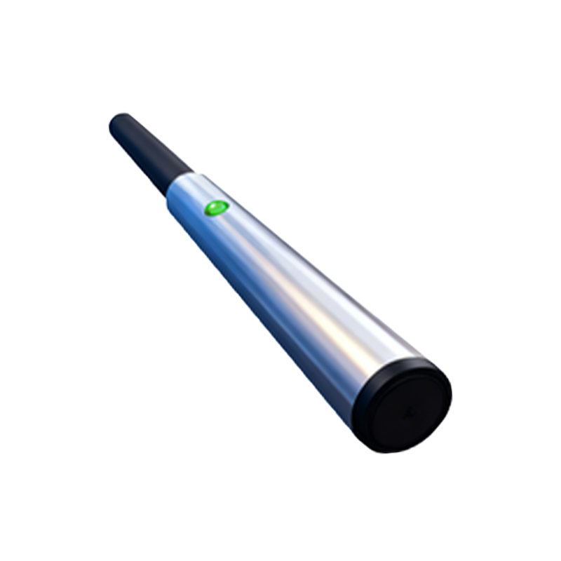
For inductive proximity sensors, which detect metallic objects, the calibration involves setting the sensing distance and often the switching hysteresis. Mount the sensor securely in its operational fixture. Using a standard target (typically a 1mm thick square of mild steel), slowly approach the sensor's sensing face along its central axis. Monitor the sensor's output using a multimeter or the PLC input indicator. Mark the precise distance at which the output switches state (e.g., from OFF to ON). This is the "operating point." Slowly retract the target and mark the distance where the output switches back. This is the "release point." The difference between these points is the hysteresis. To calibrate, many modern sensors feature a potentiometer or teach-in function. For potentiometer-adjusted sensors, use a small screwdriver to turn the pot until the output switches at the desired operating distance. For teach-in sensors, follow the manual's sequence—often involving pressing a button when the target is at the near position and again at the far position. Capacitive sensor calibration follows a similar principle but uses a dielectric target and often includes sensitivity adjustment to ignore background materials.
Calibration of Ultrasonic and Photoelectric Sensors
Ultrasonic sensors measure distance by calculating the time-of-flight of sound waves. Calibration usually involves setting the switching thresholds or analog output scaling. After secure mounting, place a reference target at the exact desired near and far switching limits. Access the sensor's parameter settings, often via pushbuttons or a software interface. Use the "teach" function to program the near point (e.g., when the target is at 10cm, press the "Set Min" button) and the far point (e.g., at 50cm, press "Set Max"). The sensor will linearly scale its output between these points. Ensure the target surface is perpendicular to the sonic beam. Environmental compensation for temperature may be required, as sound speed varies with air temperature; many advanced sensors have auto-temperature compensation. Photoelectric sensor calibration focuses on aligning the emitter and receiver (for through-beam types) or adjusting the sensitivity (for diffuse-reflective types). For diffuse sensors, use the actual target at the desired detection range. Adjust the sensitivity potentiometer or use the teach-in mode until the output reliably triggers for the target and does not trigger for background objects or ambient light changes. Laser alignment tools are invaluable for through-beam sensor setup.
Verification, Documentation, and Troubleshooting
Post-calibration verification is not optional. Perform multiple test cycles with the calibrated target, moving it through the entire sensing range. Measure the repeatability by checking if the switch point occurs at the same distance over 10-20 cycles.